
Aerobat aerodynamic configuration adopting mixing wing body

An aerodynamic shape, hybrid wing body technology, applied in the wing shape, fuselage, wing and other directions, can solve the problems of inability to arrange escape hatches, unfavorable longitudinal balance control, large sweep angle of the outer wing section, etc. Effects of increased structural weight, length, and large sweep angle

Active Publication Date: 2012-10-17
NORTHWESTERN POLYTECHNICAL UNIV
View PDF5 Cites 11 Cited by
  • Summary
  • Abstract
  • Description
  • Claims
  • Application Information

AI Technical Summary

Problems solved by technology

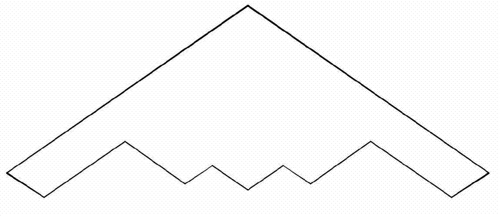
However, the wing-body fusion layout also has corresponding defects, such as the wing-body fusion layout described in the patent US-20090152392A1, the thicker central body and the transition section are prone to shock waves during transonic flight; the outer wing section has a large sweep angle, The aerodynamic efficiency is low and is not conducive to longitudinal balance control, which limits the further improvement of the aerodynamic performance of the wing-body fusion layout. The central body is short and cannot arrange more escape hatches, which makes it difficult to meet airworthiness requirements

Method used


Image

  • Aerobat aerodynamic configuration adopting mixing wing body
  • Aerobat aerodynamic configuration adopting mixing wing body
  • Aerobat aerodynamic configuration adopting mixing wing body

Examples


Embodiment Construction

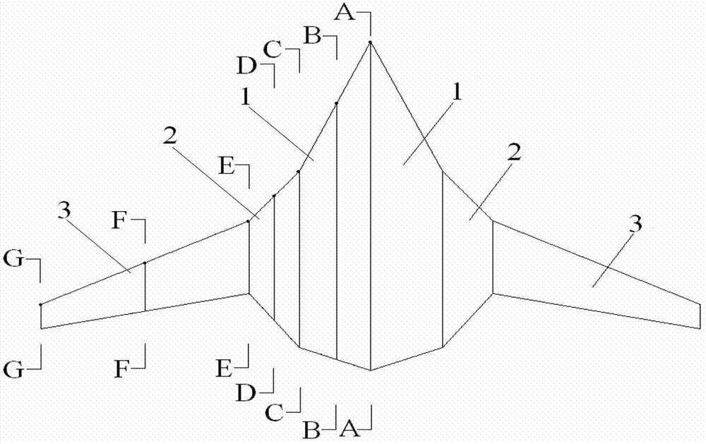
[0071] Present embodiment is a kind of aerodynamic profile that adopts the aircraft of hybrid wing body, as figure 2 As shown, this embodiment takes one side of the fuselage as an example, along the span of the fuselage, there are respectively the central fuselage 1, the transition section 2 and the outer wing section 3, and the transition section 2 is located between the central fuselage 1 and the outer wing section 3 Between them, the area ratio of the central body 1, the transition section 2 and the outer wing section 3 is 1:0.350:0.554.

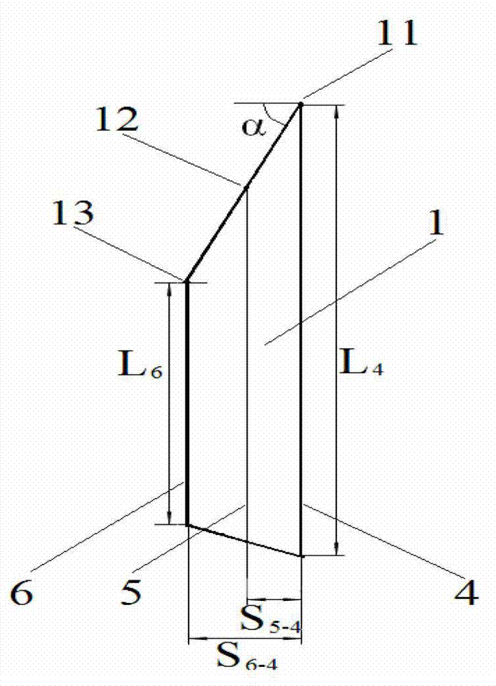
[0072] In this embodiment, the central body 1 includes a control surface 4 at the root of the central body, a control surface 5 at the middle of the central body, and a control surface 6 at the tip of the central body, and the control surface 4 at the root of the central body, the control surface 5 at the middle of the central body and The control surface 6 at the tip of the central body obtains the three-dimensional configuration of the...


PUM


Abstract

The invention relates to an aerobat aerodynamic configuration adopting a mixing wing body. According to an aerodynamic configuration on one side of a mixing wing body aerobat, a center aerobat body, a transition section and an outer wing section are respectively arranged along the expending direction of the aerobat body, the transition section is positioned between the center aerobat body and the outer wing section, and an area ratio of the center aerobat body to the transition section to the outer wing section is 1:0.350:0.554. With the technical scheme, the drag divergence Mach number Madd is 0.83, and the maximum lift-drag ratio kmax is 25, wherein the maximum lift-over-drag ratio of the mixing wing body layout is increased by 8.7% than the maximum lift-over-drag ratio of the wing body fusion layout, such that the mixing wing body layout provides higher aerodynamic efficiency and better lift-drag than the wing body fusion layout. With the present invention, the longitudinal moment static stability margin is 3%, and basically meets the self-balancing design requirement during cruise flight. Meanwhile, the aerodynamic configuration of the present invention has a large loading space.

Description

technical field [0001] The invention relates to the field of aircraft design, in particular to an aircraft aerodynamic shape using a blended wing body. Background technique [0002] With the first test flight of the giant strategic bomber B2 with wing-body integrated flying wing layout in the 1980s, people became interested in and discussed the possibility of applying this shape to civil aviation passenger aircraft or transport aircraft. Boeing began to study the technical and commercial feasibility and conceptual design research of the wing-body fusion shape in the early 1990s, and then Europe, Russia and Japan also carried out similar research one after another. Compared with the conventional layout, the advantages of the wing-body fusion layout are mainly manifested in the following points. The use of the wing-body fusion tailless layout greatly reduces the wetted area and has higher aerodynamic efficiency; due to the improvement of aerodynamic efficiency, the reduction ...

Claims


Application Information

Patent Timeline
IPC IPC(8): B64C1/00B64C3/00B64C3/10
Inventor 李沛峰张彬乾陈真利沈冬林宇褚胡冰王元元
Owner NORTHWESTERN POLYTECHNICAL UNIV
Learn More