
Dual-gas-supply inflation system applied to vacuum coating equipment and inflation method of system

A technology of vacuum coating and gas filling system, applied in vacuum evaporation coating, sputtering coating, ion implantation coating and other directions, can solve the problem of poor environmental adaptability of coating equipment, prolong the vacuuming time, affect the high vacuum degree, etc. problems, to achieve the effect of improving environmental adaptability, speeding up the rate of vacuuming, and easy installation

Active Publication Date: 2013-09-18
CHINA TRIUMPH INT ENG
View PDF4 Cites 0 Cited by
  • Summary
  • Abstract
  • Description
  • Claims
  • Application Information

AI Technical Summary

Problems solved by technology

However, the traditional inflating device in the prior art is a filter muffler connected to the inlet / outlet chamber, and the inlet / outlet chamber is directly inflated by the outside air through the filter muffler. This kind of inflator has certain limitations in use, and it is only suitable for drying For the humid atmospheric environment in some places or periods, the inlet / outlet chamber will be filled with humid air, which will affect the acquisition of high vacuum degree, prolong the vacuuming time, and affect the coating quality, which is not safe and reliable. Poor environmental adaptability of coating equipment

Method used


Image

  • Dual-gas-supply inflation system applied to vacuum coating equipment and inflation method of system
  • Dual-gas-supply inflation system applied to vacuum coating equipment and inflation method of system

Examples


Embodiment Construction

[0014] The present invention will be further described below in conjunction with accompanying drawing, and the structure and principle of this device are very clear to those skilled in the art. The examples described below are only for illustrating the present invention, and are not intended to limit the present invention.

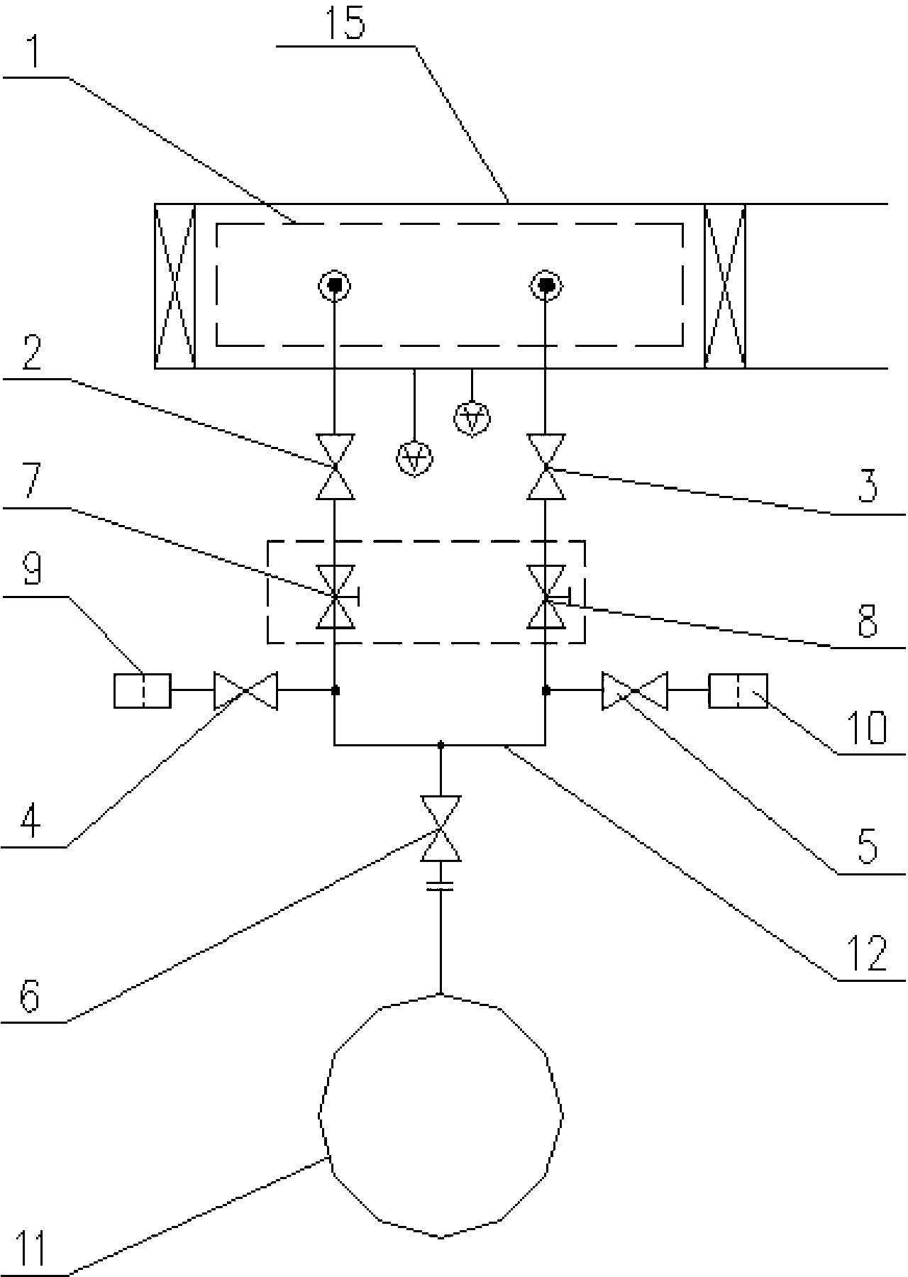
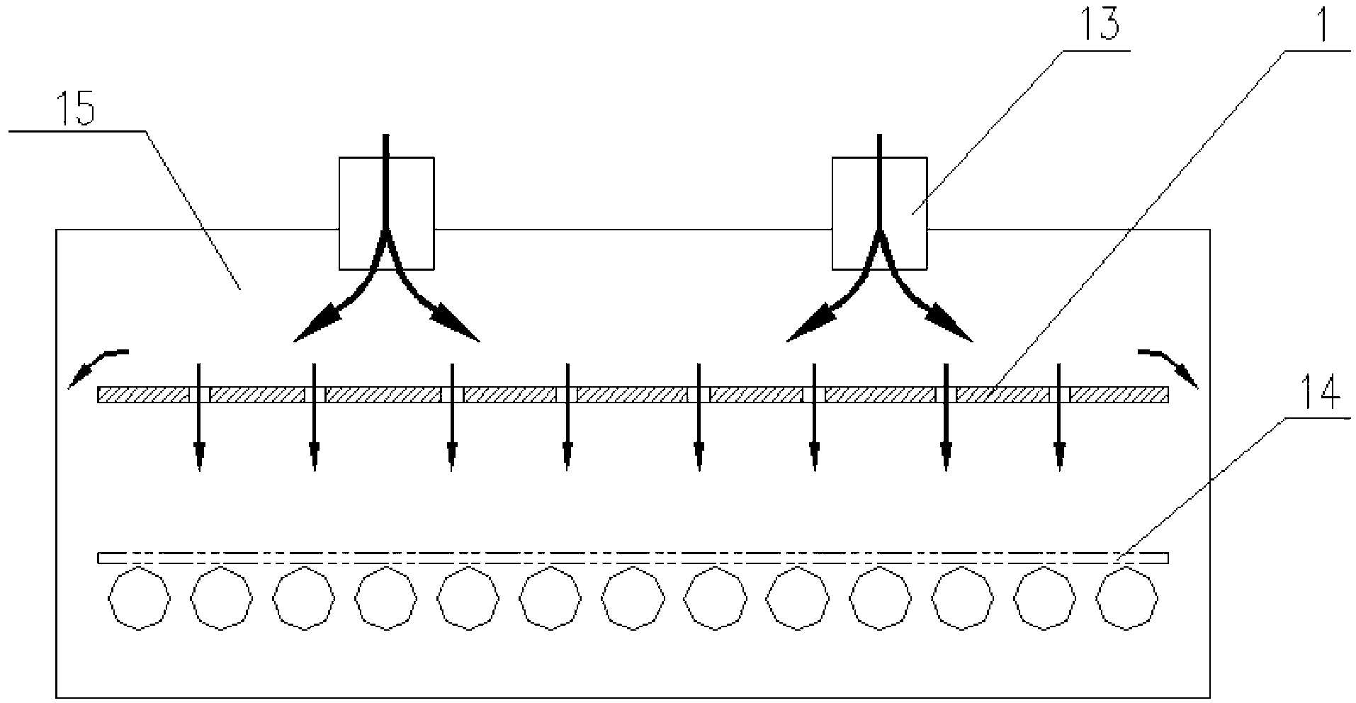
[0015] Such as figure 1 As shown, the present invention is a dual gas source inflation system for vacuum coating equipment, including an inlet / outlet chamber, a vacuum detection element is installed on the side wall of the inlet / outlet chamber, and it consists of five pneumatic butterfly valves BV1, BV2, BV3, BV4 , BV5, filter muffler 9, filter muffler 10, a dry compressed gas tank 11 and a gas buffer plate 1 composition. The components are connected by stainless steel pipes 12 . Pneumatic butterfly valve BV1 and pneumatic butterfly valve BV2 are connected in parallel and then connected in series with pneumatic butterfly valve BV5 and dry compressed air ...


PUM


Abstract

The invention relates to the technical field of coating processes, and mainly relates to a dual-gas-supply inflation system applied to vacuum coating equipment and an inflation method of the system. The inflation system comprises an inlet / outlet chamber, and the side wall of the inlet / outlet chamber is provided with vacuum detecting elements which are composed of five pneumatic butterfly valves BV1-BV5, two filtration mufflers, a dry compressed gas tank and a gas buffer board. The elements are connected by using stainless steel pipes, the BV1 is connected in parallel with the BV2 and then is connected in series with the BV5 and the dry compressed gas tank so as to form a Y-shaped inflation structure, the dry compressed gas tank is arranged at the lower part of the Y-shaped inflation structure, and the two filtration mufflers after respectively connected in series with the BV3 and the BV4, and as branches, are connected to the two sides of the Y-shaped inflation structure and between the BV1 and the BV2 as well as the BV5. The gas buffer board is arranged at the top of the inside of the inlet / outlet chamber. According to the invention, the water vapor entering the vacuum chamber can be reduced, and the vacuumizing speed of the chamber can be accelerated; the environment adaptability of coating equipment is improved, and the coating quality is improved; and the inflation system is simple in structure, and easy to install and remove.

Description

[technical field] [0001] The invention relates to the technical field of coating technology, and mainly relates to a dual gas source inflation system for vacuum coating equipment and an inflation method thereof. [Background technique] [0002] Vacuum coating mainly refers to a type of coating that needs to be carried out under a relatively high vacuum. The substrate that needs to be coated is called the substrate, and the material to be coated is called the target. The substrate and the target are in the same vacuum chamber. The process flow of vacuum coating is generally as follows: after loading the workpiece into the vacuum coating device, close the chamber of the vacuum coating device and exhaust to high vacuum, then fill in the working gas for vacuum coating, after completing the coating process, fill the chamber with One atmospheric pressure, so that the vacuum state returns to the atmospheric state, and then the chamber is opened to take out the workpiece, and the cyc...

Claims


Application Information

Patent Timeline
Patent Type & Authority Patents(China)
IPC IPC(8): C23C14/22
Inventor 彭寿葛承全罗松松葛治亮张仰平李险峰王程
Owner CHINA TRIUMPH INT ENG
Learn More