
Raising speed control energy saving system and method for excavator

An energy-saving system and excavator technology, which is applied in mechanically driven excavators/dredgers, earthmovers/shovels, construction, etc., can solve problems such as fuel consumption, deterioration of work performance, and heating of hydraulic systems, to avoid The effect of power loss

Active Publication Date: 2012-10-17
SANY HEAVY MACHINERY
View PDF5 Cites 20 Cited by
  • Summary
  • Abstract
  • Description
  • Claims
  • Application Information

AI Technical Summary

Problems solved by technology

The problem caused by this operation is that if the excavator does not use the workload for a period of time after it is in gear, it will consume too much fuel due to the high-speed rotation of the engine, which will cause problems such as heating of the hydraulic system and deterioration of work performance.

Method used


Image

  • Raising speed control energy saving system and method for excavator
  • Raising speed control energy saving system and method for excavator
  • Raising speed control energy saving system and method for excavator

Examples


no. 1 example

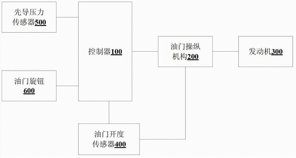
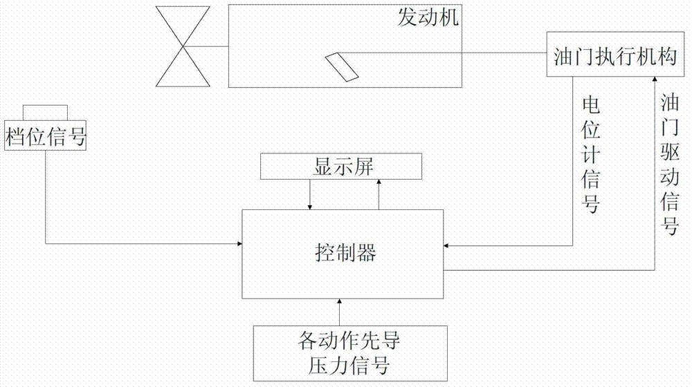
[0026] refer to figure 1 and figure 2 .

[0027] The speed-up control and energy-saving system of the excavator in this embodiment includes: a pilot pressure sensor 500 , a controller 100 and an accelerator control mechanism 200 .

[0028] Among them, the pilot pressure sensor 500 is used to detect the pilot pressure signal of each action of the excavator; the controller 100 is connected with the throttle knob 600 of the excavator and the pilot pressure sensor 500; In the case of no-load speed control signal; and, after obtaining the working gear, if the pilot pressure signal is further detected, the target speed control signal is sent; the throttle control mechanism 200 is connected with the controller 100 for The load speed control signal or the target speed control signal controls the opening and closing degree of the accelerator, so as to control the speed of the engine 300 to be between the no-load speed and the target speed.

[0029] Wherein, the no-load rotational s...

no. 2 example

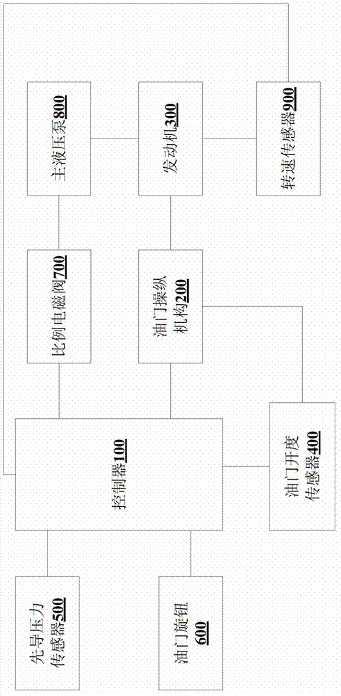
[0036] refer to image 3 and Figure 4 .

[0037]The speed-up control and energy-saving system of the excavator in this embodiment includes: a pilot pressure sensor 500 , a controller 100 , an accelerator operating mechanism 200 , an accelerator opening sensor 400 , a proportional solenoid valve 700 and a speed sensor 900 .

[0038] Among them, the pilot pressure sensor 500 is used to detect the pilot pressure signal of each action of the excavator; the controller 100 is connected with the throttle knob 600 of the excavator and the pilot pressure sensor 500; In the case of no-load speed control signal; and, after obtaining the working gear, if the pilot pressure signal is further detected, the target speed control signal is sent; the throttle control mechanism 200 is connected with the controller 100 for The load speed control signal or the target speed control signal controls the opening and closing degree of the accelerator, so as to control the speed of the engine 300 to ...


PUM


Abstract

The invention discloses a raising speed control energy saving system and a raising speed control energy saving method for an excavator. The raising speed control energy saving system comprises a pilot pressure sensor, a controller and an accelerator control mechanism. The pilot pressure sensor is used for detecting pilot pressure signals of all actions of the excavator; the controller is connected with an accelerator knob and the pilot pressure sensor of the excavator; the accelerator control mechanism is connected with the controller; and the controller controls the openness of an accelerator based on working gears transferred by the accelerator knob and load conditions detected by the pilot pressure sensor according to different stages by the accelerator control mechanism. By the system and the method, the power loss of an engine is avoided, and the engine and a main pump run in the most economic state. Moreover, the efficiency of large excavators is improved, and oil consumption is reduced under the condition that auxiliary equipment is not added.

Description

technical field [0001] The invention relates to the field of engineering machinery, in particular to an excavator speed-up control energy-saving system and method. Background technique [0002] Large-scale hydraulic excavators are important construction machinery, which have the advantages of large digging force, high production efficiency, strong environmental adaptability, and wide adaptability. [0003] However, due to the complex operating conditions of large hydraulic excavators, frequent load changes and large change ranges during the operation process, there are many links of energy loss. For example, in the prior art, after the excavator is in gear, the engine speed will directly increase to the target speed of the gear, and when the load is connected, the engine speed will drop freely on the basis of the target speed. The problem caused by this operation is that if the excavator does not use the workload for a period of time after it is in gear, it will consume too...

Claims


Application Information

Patent Timeline
Patent Type & Authority Applications(China)
IPC IPC(8): E02F9/20
CPCE02F9/20E02F3/43E02F9/22E02F3/42E02F9/2066E02F9/2246
Inventor 尹满义黄玉松吴高丰
Owner SANY HEAVY MACHINERY
Learn More