Method and system for providing air to an engine

An engine and air pipe technology, applied in engine components, combustion engines, engine control, etc., can solve problems such as compressor surge, reduce noise and improve fuel economy.

Inactive Publication Date: 2012-10-17
FORD GLOBAL TECH LLC
View PDF4 Cites 12 Cited by
  • Summary
  • Abstract
  • Description
  • Claims
  • Application Information

AI Technical Summary

Problems solved by technology

However, compressor surge occurs when the flow through the compressor is low and the pressure differential across the compressor is relatively high

Method used


Image

  • Method and system for providing air to an engine
  • Method and system for providing air to an engine
  • Method and system for providing air to an engine

Examples


Embodiment Construction

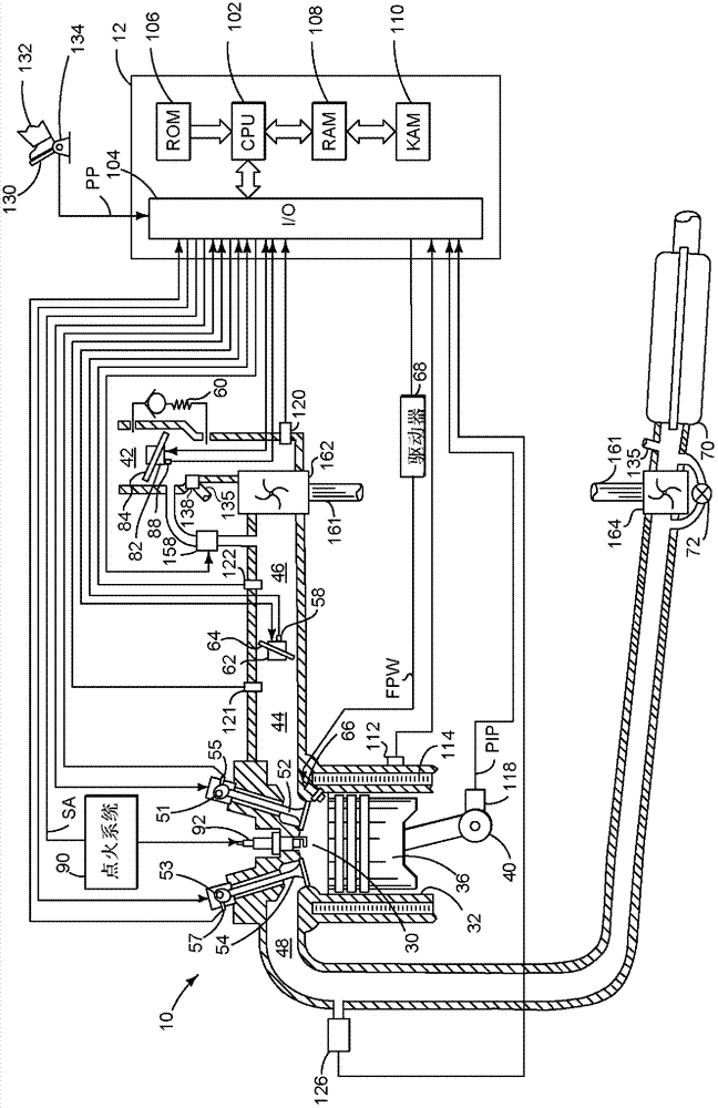
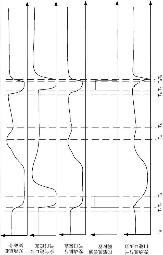
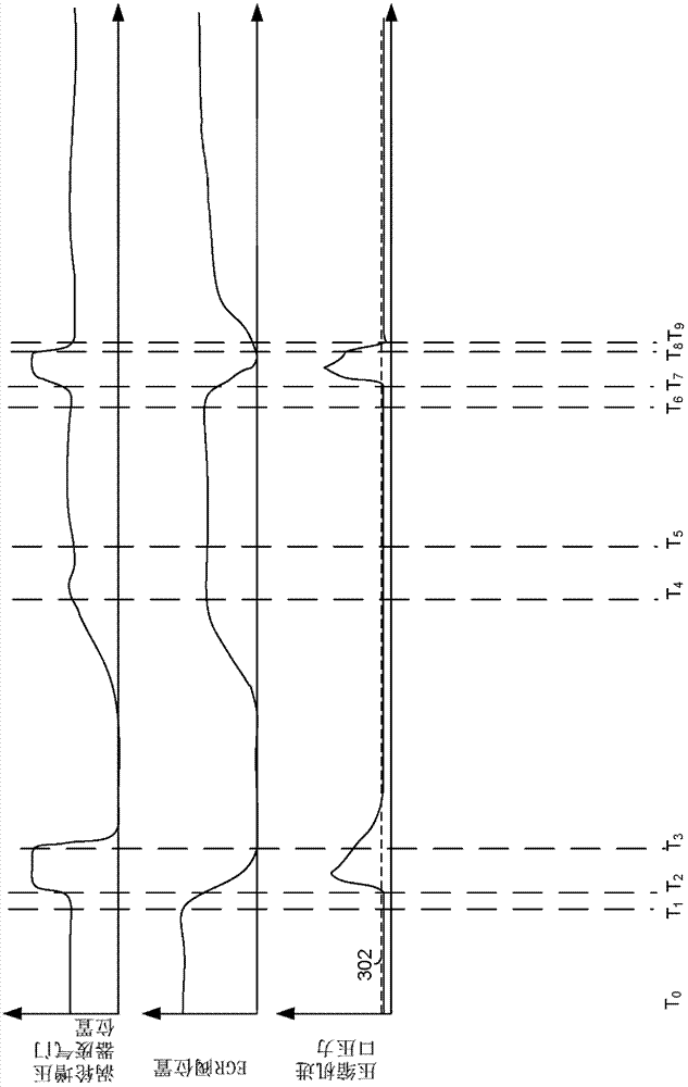
[0020] This instruction deals with supplying air to the engine. In particular, the present description provides a method for reducing the potential for noise generation during low flow and higher compression ratio conditions across the compressor. figure 1 An example system for supplying air to an engine is shown. Figure 2 to Figure 5 The associated simulated signals are shown when air is supplied to the engine. Image 6 show as Figure 2 to Figure 5 The method and controls for providing air to the engine are shown.

[0021] refer to figure 1 , an internal combustion engine 10 comprising a plurality of cylinders is controlled by an electronic engine controller 12, at figure 1 A cylinder of internal combustion engine 10 is shown in . Engine 10 includes combustion chamber 30 and cylinder walls 32 with piston 36 positioned therein and connected to crankshaft 40 . Combustion chamber 30 is shown communicating with intake manifold 44 and exhaust manifold 48 via intake valve 5...


PUM


Abstract

Systems and methods for supplying air to an engine are disclosed. In one example, an air inlet throttle is at least partially closed in response to a change in engine torque request. In another example, the air inlet throttle is adjusted in conjunction with adjusting an engine throttle. The approach can reduce compressor noise and may reduce the possibility of compressor surge.

Description

technical field [0001] The present invention relates to methods and systems for supplying air to an engine. Background technique [0002] Engine efficiency can be improved while providing a desired engine output capability by reducing engine displacement and compressing air supplied to the engine. Reducing engine displacement reduces engine pumping losses, and compressing engine air intake increases power output from smaller displacement engines. Thus, the smaller displacement engine can provide improved fuel economy compared to the larger displacement engine while providing a similar amount of power to the larger displacement engine. However, compressor surge occurs when the flow through the compressor is low and the pressure differential across the compressor is relatively high. Surge is undesirable for several reasons, including that it can cause undesired noise from the engine intake system due to surge. Contents of the invention [0003] The inventors have recogniz...

Claims


Application Information

Patent Timeline
Patent Type & Authority Applications(China)
IPC IPC(8): F02D9/08F02D21/08F02D23/00
CPCF02B37/16F02M25/0709F02B37/18F02D2250/18F02D41/005F02D41/0007F02D2041/0017F02D41/1497Y02T10/144F02M26/06Y02T10/12F02D41/0005Y02T10/40
Inventor J·N·阿勒瑞J·A·多尔因R·D·普斯夫D·J·刘易斯
Owner FORD GLOBAL TECH LLC
Why Eureka
Try Eureka