Electronic expansion valve

A technology of electronic expansion valve and valve needle, which is applied in the direction of lift valve, valve device, lighting and heating equipment, etc., can solve the problems of high material cost, high processing difficulty and low processing efficiency of valve seat 1', so as to improve the sealing effect. The effect of performance and reliability of work, reduction of material cost, and improvement of processing efficiency

Active Publication Date: 2012-10-17
ZHEJIANG SANHUA INTELLIGENT CONTROLS CO LTD
View PDF8 Cites 28 Cited by
  • Summary
  • Abstract
  • Description
  • Claims
  • Application Information

AI Technical Summary

Problems solved by technology

[0006] First, since the valve needle guide hole 1'2 with a smaller aperture is opened on the valve seat 1', and the two ends of the valve seat 1' need to be provided with a valve chamber 1'1 and a nut installation hole 1'3a with a larger aperture, Therefore, in the processing process, the valve seat 1' needs to be clamped twice, and the nut installation hole 1'3a and the valve cavity 1'1 are respectively processed from the two ends of the valve seat 1', which will cause the nut installation hole 1' The coaxiality between 3a and the valve cavity 1'1 is poor, which will affect the coaxiality between the valve needle 6' and the valve port 2'1, and reduce the sealing performance and working reliability of the product
[0007] Second, as mentioned in the previous paragraph, the valve seat 1' needs to be clamped and processed twice before the nut mounting hole 1'3a and the valve cavity 1'1 can be processed, so the processing efficiency is very low and the processing is difficult Larger; especially in order to improve the corrosion resistance of the product and the reliability of the weld seam, when the valve seat is made of stainless steel, the processing efficiency of the valve seat 1′ will be lower and the processing difficulty will be greater
[0008] Third, the valve seat 1' is provided with a protruding part 1'3 extending into the magnetic rotor 3', and the protruding part 1'3 is provided with a nut installation hole 1'3a with large axial and radial dimensions , thus resulting in a large material cost for the valve seat 1'

Method used


Image

  • Electronic expansion valve
  • Electronic expansion valve
  • Electronic expansion valve

Examples


Embodiment Construction

[0045] The core of the present invention is to provide an electronic expansion valve. The structural design of the electronic expansion valve can improve the coaxiality between the corresponding holes of the valve seat on the one hand, and can improve the processing efficiency of the valve seat and reduce its material cost on the other hand. expenditure.

[0046] In order to enable those skilled in the art to better understand the technical solutions of the present invention, the present invention will be further described in detail below in conjunction with the accompanying drawings and specific embodiments.

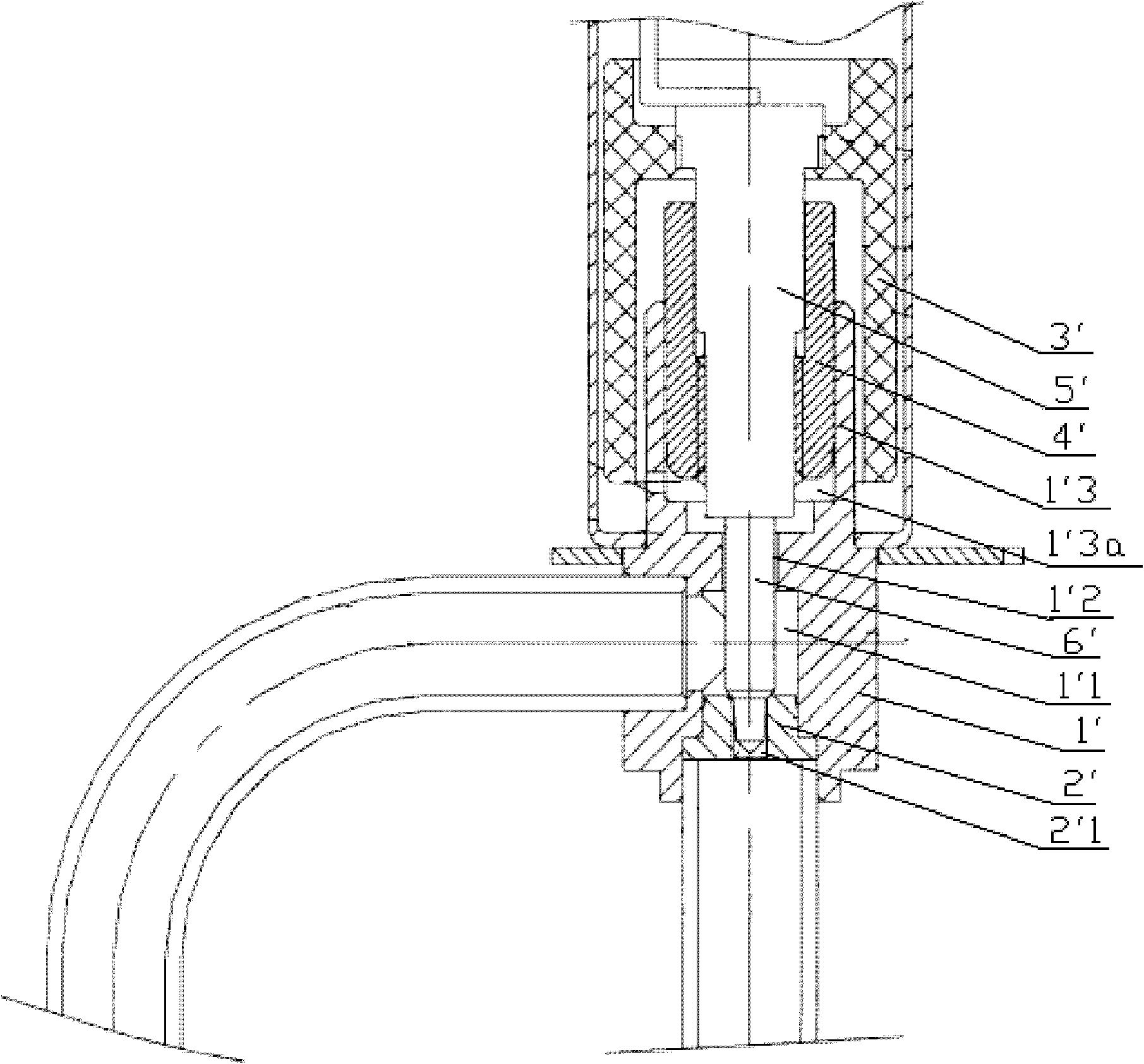
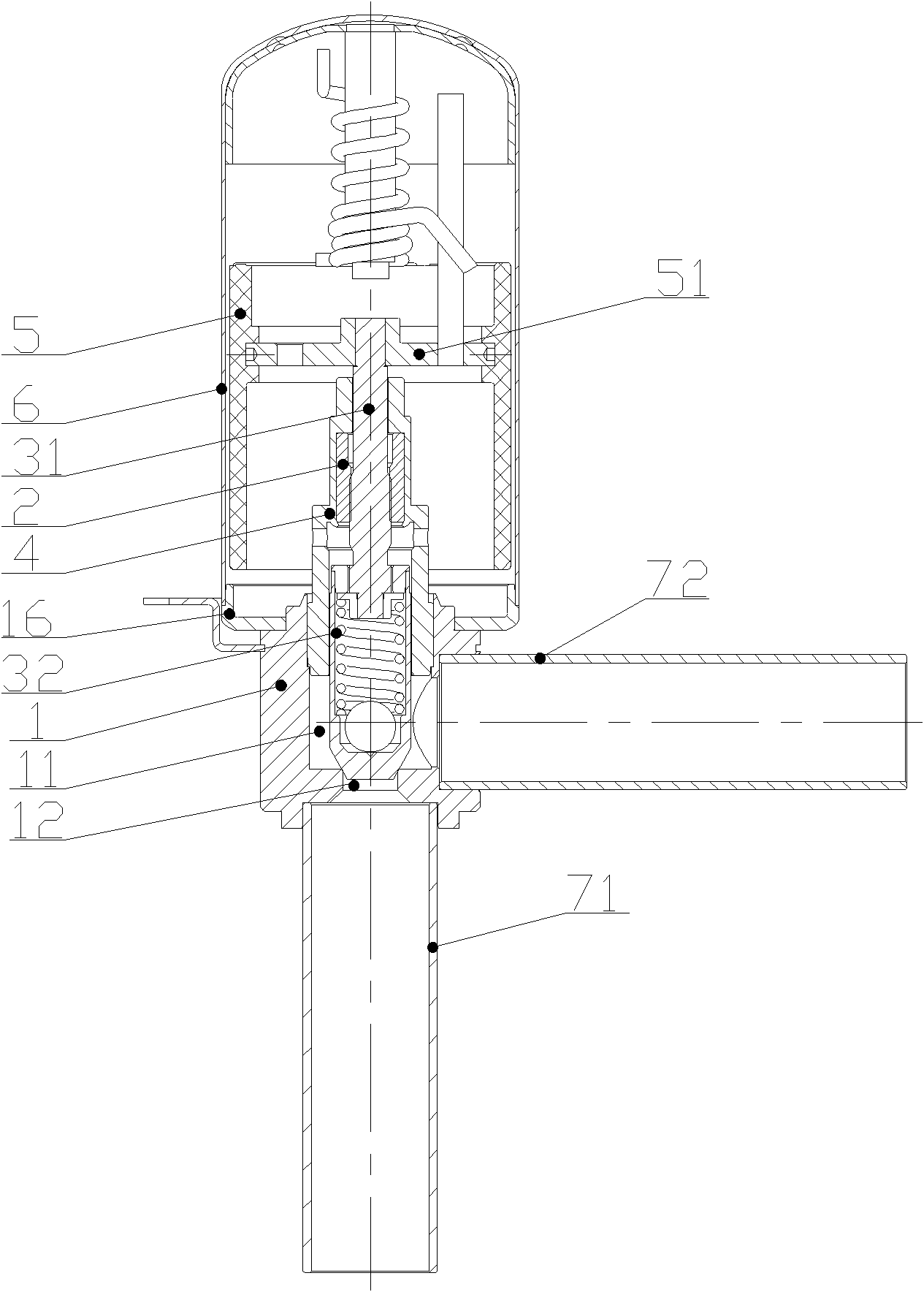
[0047] Please refer to figure 2 , image 3 , Figure 4 and Figure 5 , figure 2 It is a schematic structural diagram of the electronic expansion valve in the first embodiment of the present invention; image 3 for figure 2 Schematic diagram of the seat assembly of the electronic expansion valve; Figure 4 for figure 2 Schematic diagram of the bearing seat of t...


PUM


Abstract

The invention discloses an electronic expansion valve which comprises a valve seat (1), a nut (2) and a valve needle assembly and also comprises a bearing block (4), wherein the valve seat (1) is provided with a valve cavity (11) and a valve port (12); the nut (2) is connected with the valve seat (1); the valve needle assembly is matched with the nut (2) through a screw (31) via a thread; a bearing block mounting hole (13) for installing the bearing block (4) is formed on the valve seat (1); the nut (2) is connected with the valve seat (1) through the bearing block (4); and a valve needle guide hole (41) is formed on the bearing block (4), and a valve needle (32) of the valve needle assembly passes through the valve needle guide hole (41) and is matched with the valve port (12). According to the structure design of the electronic expansion valve, on one hand, the coaxiality between corresponding holes of the valve seat (1) can be improved, on the other hand, the processing efficiency of the valve seat (1) can be improved, and the expenditure of material cost is reduced.

Description

technical field [0001] The invention relates to the technical field of fluid control components, in particular to an electronic expansion valve. Background technique [0002] In the technical field of refrigeration and heating, the electronic expansion valve is the refrigerant flow control part of the refrigeration and heating equipment. flow. [0003] In the prior art, the patent No. 200520101881.2 discloses an electronic expansion valve, please refer to figure 1 , figure 1 It is a structural schematic diagram of an electronic expansion valve in the prior art. [0004] In this prior art, such as figure 1 As shown, the electronic expansion valve includes a valve seat 1', the valve seat 1' is provided with a valve chamber 1'1, the lower end of the valve chamber 1'1 is equipped with a valve core seat 2', and a valve core seat 2' is provided with a valve port 2'1; in addition, the valve seat 1' is also provided with a valve needle guide hole 1'2, and the upper end of the v...

Claims


Application Information

Patent Timeline
Patent Type & Authority Applications(China)
IPC IPC(8): F16K1/02F16K1/32F16K1/42F25B41/06
CPCY02B30/72Y02B30/70
Inventor 孙占龙魏先让詹才意
Owner ZHEJIANG SANHUA INTELLIGENT CONTROLS CO LTD
Why Eureka
Try Eureka