Supercharge Your Innovation With Domain-Expert AI Agents!

Heat pump system and heat pump unit controlling method

A technology of a heat pump system and a heat pump device, which is applied in the field of compressor control, can solve the problems of cost, no heating mixing valve, variable flow circulation pump, etc., and achieve the effect of promoting energy saving

Active Publication Date: 2014-08-06
MITSUBISHI ELECTRIC CORP
View PDF5 Cites 0 Cited by
  • Summary
  • Abstract
  • Description
  • Claims
  • Application Information

AI Technical Summary

Problems solved by technology

[0010] However, it costs money to install heating mixing valves and variable flow circulation pumps
In addition, when building a heating system in Europe and other places, because the local installer randomly selects the circulation pump, etc., it is possible that the heating mixing valve and the variable flow circulation pump are not installed.

Method used


Image

  • Heat pump system and heat pump unit controlling method
  • Heat pump system and heat pump unit controlling method
  • Heat pump system and heat pump unit controlling method

Examples


Embodiment approach 1

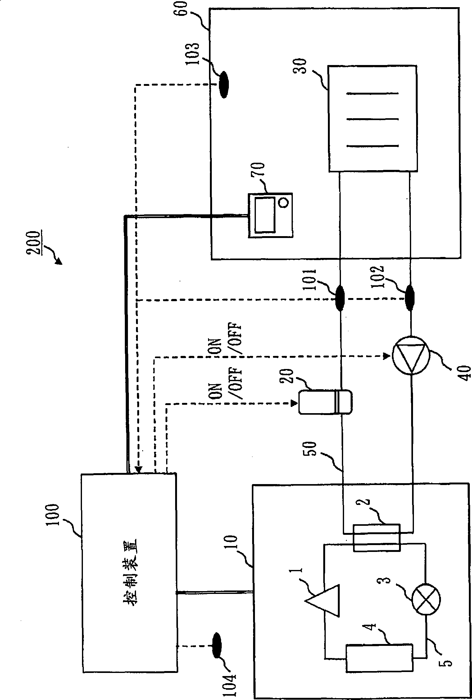
[0025] figure 1 It is a structural diagram of the heat pump system 200 of Embodiment 1.

[0026] The heat pump system 200 includes a heat pump device 10 , an auxiliary heat source 20 , a radiator 30 (an example of a fluid utilization device) installed in an indoor space 60 , and a pump 40 , which are sequentially connected by a fluid pipe 50 . In addition, the fluid piping 50 is connected to the heat exchanger 2 equipped in the heat pump device 10 . In addition, water (an example of fluid) flows inside the fluid piping 50 .

[0027] In addition, in the indoor space 60 where the radiator 30 is installed, a remote controller 70 for inputting a set temperature and the like is provided.

[0028] The heat pump device 10 has a heat pump cycle in which a compressor 1 , a heat exchanger 2 , an expansion mechanism 3 , and a heat exchanger 4 are sequentially connected through a refrigerant pipe 5 . The refrigerant circulates in the order of the compressor 1, the heat exchanger 2, the...


PUM


Abstract

The present invention provides a heat pump system and a control method of the heat pump system, aiming at continuously operating the heat pump device without using special equipment. The control device (100) sequentially calculates the rate of change (inflow temperature change rate) of the inflow temperature into the radiator (30) every predetermined time and the outflow rate from the radiator (30) from the start of operation of the compressor (1). The rate of change of temperature per predetermined time (outflow temperature change rate). In addition, the control device (100) sets the inflow temperature when the difference between the inflow temperature change rate and the outflow temperature change rate is below the change rate threshold value as the minimum temperature, sets the temperature above the minimum temperature as the target temperature, and controls the compressor (1) Make the inflow temperature the target temperature.

Description

technical field [0001] The present invention relates to a control technology of a compressor included in a heat pump system. In particular, the present invention relates to a compressor control technique when the load is relatively low such as in the middle of a season. Background technique [0002] There is a heat pump heating system that generates hot water in a heat pump device and supplies the generated hot water to a plate heater or the like to perform heating operation. [0003] In the heat pump heating system, the target temperature is set according to the load during operation, etc., and the heat pump device is controlled so that the temperature of hot water (inflow temperature) supplied to the plate heater or the like becomes the target temperature. At this time, the target temperature is set to be a temperature between the minimum temperature and the maximum temperature predetermined before each heat pump device leaves the factory. [0004] In the heat pump heati...

Claims


Application Information

Patent Timeline
Patent Type & Authority Patents(China)
IPC IPC(8): F25B30/02F25B49/02
CPCF24D2200/123F24D3/02F24D2200/08F24D3/18F24D19/1039F24D11/0214Y02B30/12F24H15/37F24H15/38
Inventor 松泽耕司
Owner MITSUBISHI ELECTRIC CORP
Features
  • R&D
  • Intellectual Property
  • Life Sciences
  • Materials
  • Tech Scout
  • Unparalleled Data Quality
  • Higher Quality Content
  • 60% Fewer Hallucinations
Learn More