Supercharge Your Innovation With Domain-Expert AI Agents!

Ejecting air flue of instant freezer

A quick-freezing machine and air duct technology, applied in lighting and heating equipment, cooling fluid circulation devices, household appliances, etc., can solve the problems of uneven freezing and slow efficiency, and achieve the effect of uniform freezing and high freezing speed.

Inactive Publication Date: 2012-10-17
郑州亨利制冷设备有限公司
View PDF5 Cites 8 Cited by
  • Summary
  • Abstract
  • Description
  • Claims
  • Application Information

AI Technical Summary

Problems solved by technology

[0003] The technical problem to be solved by the present invention is that the jet air channel of the existing linear quick-freezing machine freezes unevenly and has low efficiency, and provides a quick-freezing machine jet duct with uniform freezing and high freezing efficiency

Method used


Image

  • Ejecting air flue of instant freezer
  • Ejecting air flue of instant freezer
  • Ejecting air flue of instant freezer

Examples


Embodiment 1

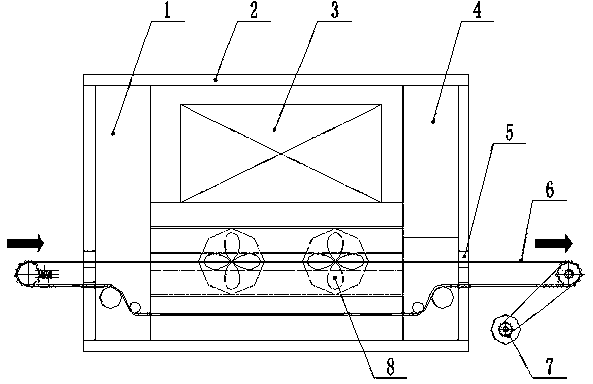
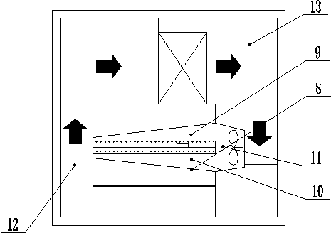
[0018] like figure 1 and figure 2 As shown, the spray air duct of the quick-freezing machine in this embodiment includes a heat preservation body 2 and a conveyor belt 6, a heat exchanger 3 and a heat exchange fan 8 are arranged in the heat preservation body 2, and the input end of the heat exchanger 3 is connected to the return air duct 12 , The output end of the heat exchanger 3 is provided with an air supply channel 13, the air supply channel 13 is connected to the air distribution cavity 11, and the upper air injector 9 and the lower air injector 10 at the port of the air distribution cavity 11 are wedge-shaped. The heat exchange fan 8 is arranged in the air distribution cavity 11 .

[0019] Both ends of the thermal insulation body 2 are respectively provided with an inlet cold and heat balance room 1 or / and an outlet cold and heat balance room 4 . Due to the large temperature difference between the inside and outside of the heat preservation body, the moment when the f...

Embodiment 2

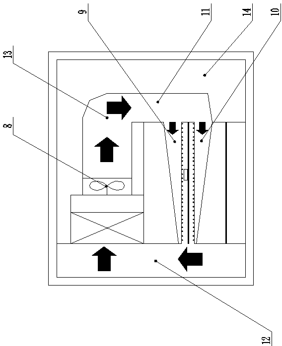
[0024] like image 3 and Figure 4 As mentioned above, the heat exchange fan 8 in this embodiment is arranged at the outlet of the heat exchanger 3 , and the maintenance channel 14 is provided in the heat preservation body 2 . Other structure and usage mode are the same as embodiment 1.

[0025] The inspection channel 14 is reserved, which can facilitate the staff to carry out inspection and maintenance work.

[0026] Compared with Embodiment 1, in this embodiment, the heat exchange fan 8 is arranged at the outlet of the heat exchanger, which can improve the cold air utilization efficiency.

Embodiment 3

[0028] like Figure 5 As shown, the heat exchange fan 8 in this embodiment is arranged at the outlet of the heat exchanger 3, and the heat preservation body 2 is provided with a deflector 15, and other structures and usage methods are the same as in the first embodiment.

[0029] In this embodiment, deflectors 15 are provided to allow cold air to enter the air distribution chamber smoothly, and the heat exchange fan 8 is arranged at the outlet of the heat exchanger, which can not only improve the utilization rate of cold air, but also reduce Production costs.


PUM


Abstract

The invention discloses an ejecting air flue of an instant freezer. The ejecting air flue comprises a heat preservation body and a conveying belt, wherein a heat exchanger and a heat exchange fan are arranged in the heat preservation body; an input end of the heat exchanger is connected with an air return duct, and an output end of the heat exchanger is provided with an air delivery duct; the air delivery duct is connected with an air distribution cavity; and an upper air ejector and a lower air ejector of a port of the air distribution cavity are wedged. In the ejecting air flue, the upper air ejector an the lower air ejector have wedged structures, air which flows out of the air distribution cavity is divided into an upper path and a lower path which form high-speed air flow through the upper air ejector and the lower air ejector to impact surface of a food respectively. Since the upper air ejector and the lower air ejector are wedged, pressure at each place in the ejector is the same, and cold air ejected to each position on the surface of the food is also the same, the obtained food is uniformly frozen, and the ejecting air flue has high freezing speed, namely the freezing speed is about twice that of the conventional linear instant freezer.

Description

technical field [0001] The invention relates to a quick-freezing machine, in particular to a spray air duct of the quick-freezing machine. Background technique [0002] The quick-freezing machine is a commonly used machine in the food processing industry, and the jet duct is the key to determine the freezing effect of the quick-freezing machine. The working process of the spray air duct is to place the food that needs to be frozen on the conveyor belt, and bring the food into the quick-freezer through the conveyor belt. The cold air in the quick-freezer sprays cold air to the upper and lower surfaces of the food at the same time to realize the freezing of the food. However, traditional quick-freezing machines are mostly straight-line quick-freezing machines. The upper and lower air injectors have a rectangular section, and the cold air is sprayed onto the upper and lower surfaces of the food by the upper and lower air injectors after coming out of the air distribution chambe...

Claims


Application Information

Patent Timeline
IPC IPC(8): F25D17/08
Inventor 董德永郭明涛
Owner 郑州亨利制冷设备有限公司
Features
  • R&D
  • Intellectual Property
  • Life Sciences
  • Materials
  • Tech Scout
  • Unparalleled Data Quality
  • Higher Quality Content
  • 60% Fewer Hallucinations
Learn More