Vision-based steel ball surface defect detection apparatus and detection method

A defect detection and steel ball technology, which is used in measuring devices, material analysis by optical means, instruments, etc., can solve the problems that the spherical surface cannot be fully unfolded, the cleaning steps are added, and the unfolding device is complicated, and the detection results are stable and reliable. Improve the detection rate and apply a wide range of effects

Inactive Publication Date: 2014-04-30
TIANJIN UNIV
View PDF1 Cites 12 Cited by
  • Summary
  • Abstract
  • Description
  • Claims
  • Application Information

AI Technical Summary

Problems solved by technology

The expansion device of this method is complicated, and the expansion is random, which cannot guarantee the complete expansion of the spherical surface; the immersion of the liquid will cause some pollution to the steel ball itself, and the collected images are prone to impurities that affect the evaluation. Not only does the liquid need to be replaced regularly, but also follow-up cleaning steps are added. ;The range of detection balls is large and medium-sized steel balls, not suitable for miniature steel balls below 3mm

Method used


Image

  • Vision-based steel ball surface defect detection apparatus and detection method
  • Vision-based steel ball surface defect detection apparatus and detection method
  • Vision-based steel ball surface defect detection apparatus and detection method

Examples


Embodiment Construction

[0062] The visual-based detection method and device for steel ball surface defects of the present invention will be described in detail below in conjunction with the embodiments and the drawings.

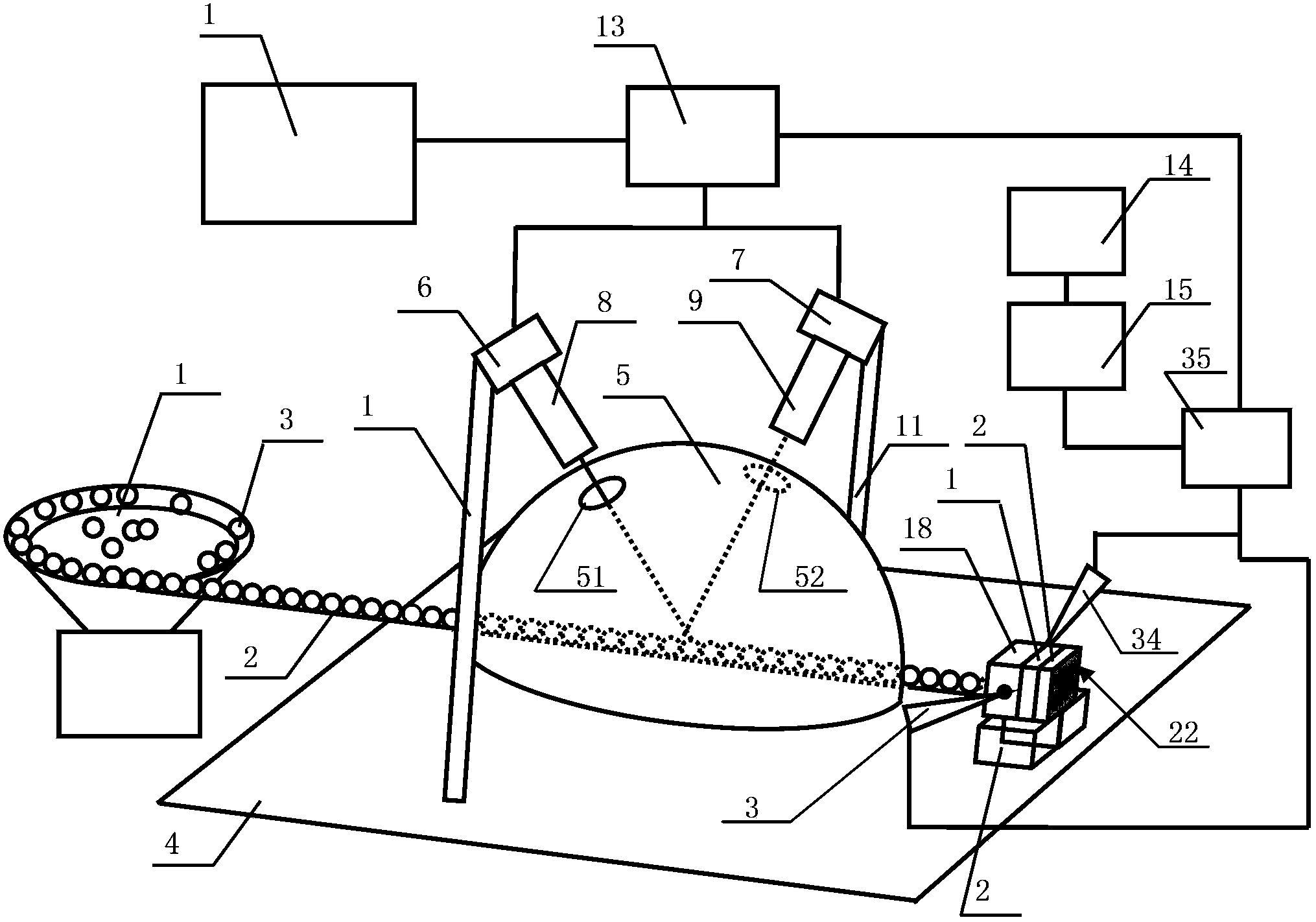
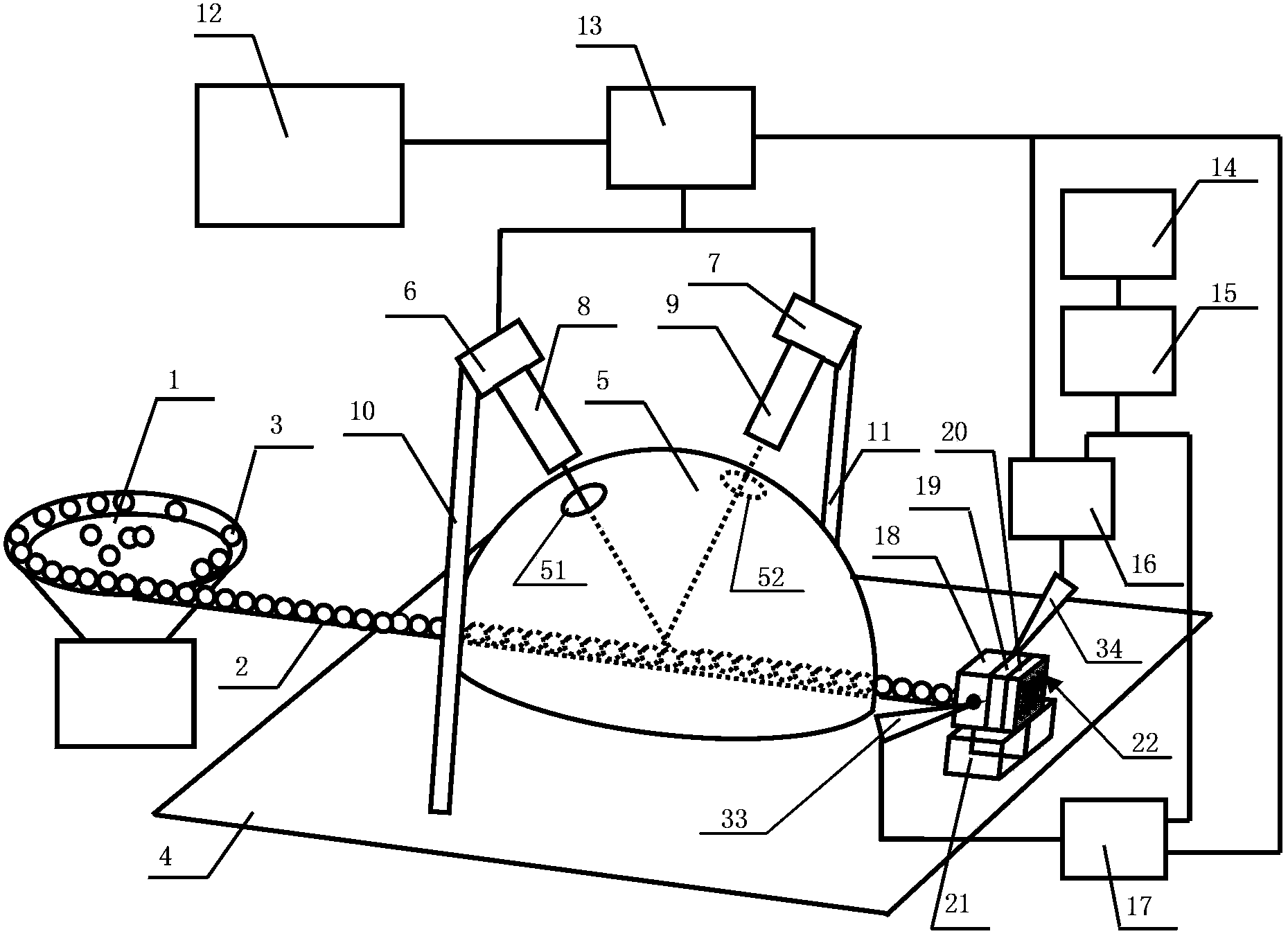
[0063] In the vision-based steel ball surface defect detection method and device of the present invention, the sorting machine uses two industrial cameras to simultaneously collect the steel ball surface images, and the collected images are processed in real time in the PC to determine whether there are defects. The PCI acquisition card connected to the PC sends control commands to realize template image acquisition, real-time acquisition of steel ball images, steel ball queue stepping, steel ball sorting and delivery to the sorting box.

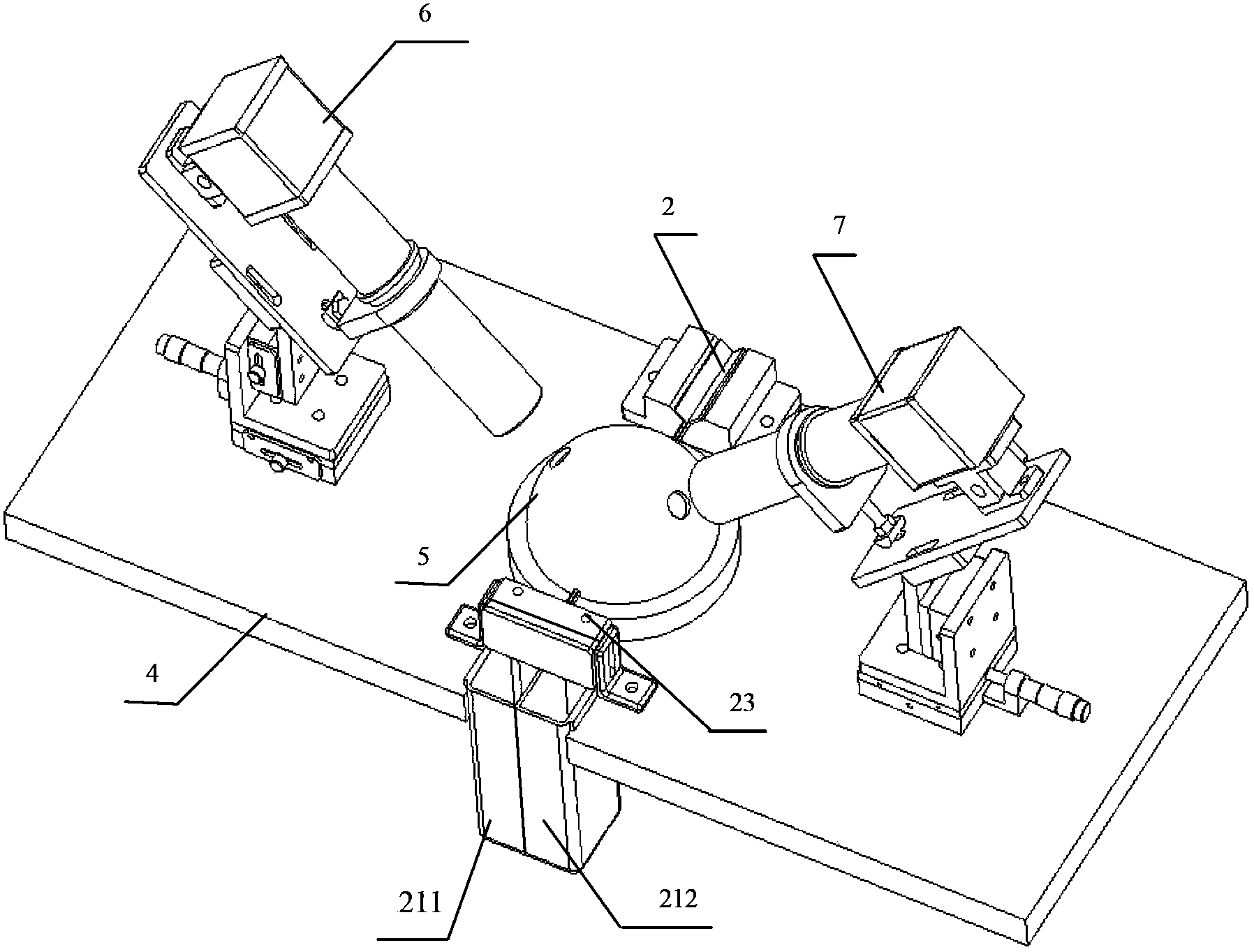
[0064] Such as figure 1 , figure 2 , image 3 As shown, the vision-based steel ball surface defect detection device of the present invention includes a workbench 4, and the workbench 4 is provided with a light source 5 composed of a light source bowl c...


PUM


Abstract

The invention relates to a vision-based steel ball surface defect detection apparatus and a vision-based steel ball surface defect detection method. According to the apparatus, a light source is arranged on a work bench; a left camera and a right camera are symmetrically arranged on the two sides of the light source; a vibration material supplying tray and a material conveying channel are arranged behind the light source; the material conveying channel penetrates a light source bowl cover and extends to the front side of the light source; a sorting mechanism and collecting boxes positioned below the sorting mechanism are arranged on the front side of the light source; a discharging terminal of the material conveying channel is inserted into a feeding terminal of the sorting mechanism; the left camera and the right camera are respectively connected to a PCI card, and the PCI card is respectively connected to a computer and a pneumatic unit; and the output end of the pneumatic unit is connected to the sorting mechanism. The method comprises the steps that: a template image is collected; the steel balls are driven to move along the material conveying channel; the left camera and the right camera respectively acquire steel ball images 3 times, and the images are compared with the template image; according to the comparison results, the PCI card controls a solenoid valve which controls the sorting mechanism, such that the detected steel ball can fall into a corresponding collecting box. According to the invention, the detection process is fully automated, and the defect detection is accurate and highly efficient.

Description

Technical field [0001] The invention relates to a detection of surface defects of steel balls. In particular, it relates to a visual-based detection method and device for surface defects of steel balls. Background technique [0002] Steel balls are widely used both as bearing balls and general rolling elements. The surface quality of the steel ball directly affects the accuracy and service life of the bearing. At present, most of the methods used by domestic steel ball manufacturers to detect steel ball surface defects are light inspection in the traditional sense, that is, the inspector moves the steel ball in the shovel by hand, and uses the naked eye (or low-power magnifying glass) under the light. ) Observe and remove defective balls manually. In the face of batch inspection requirements, the lamp inspection method not only has low inspection efficiency, but also cannot guarantee the full deployment of the ball surface by manual pushing, which is easy to miss or misdetect,...

Claims


Application Information

Patent Timeline
Patent Type & Authority Patents(China)
IPC IPC(8): G01N21/892
Inventor 栗琳王仲裴芳莹李云利
Owner TIANJIN UNIV
Why Eureka
Try Eureka