An Ultrasonic Surface Wave Detection Method for Fatigue Cracks in Locomotive Connecting Rods

An ultrasonic surface wave and ultrasonic technology, which is applied in the analysis of solids using sonic/ultrasonic/infrasonic waves, can solve problems such as poor operability, reduced locomotive running rate, and missed detection, and avoid overall disassembly work, detection rate and The effect of satisfying reliability and improving detection efficiency

Active Publication Date: 2016-04-27
CRRC QISHUYAN INSTITUTE CO LTD +1
View PDF3 Cites 0 Cited by
  • Summary
  • Abstract
  • Description
  • Claims
  • Application Information

AI Technical Summary

Problems solved by technology

However, the position and structure of the locomotive connecting rod are relatively complicated, and the disassembly and installation process are very complicated. Not only is the labor intensity high, but also the detection efficiency is low.
However, if the disassembled connecting rod is used for detection, the running rate of the locomotive will be greatly reduced, which will seriously affect the normal transportation of the railway.
At present, the conventional surface non-destructive testing includes penetrant testing, eddy current testing, shear wave testing and other methods. Penetrant testing also needs to remove the connecting rod from the locomotive before testing, which has poor field operability and low testing efficiency.
Although the eddy current test can theoretically meet the test of the connecting rod on the locomotive, in order not to disassemble the test, the environment and surface conditions of the connecting rod lead to a very obvious lift-off effect of the eddy current test, which makes it difficult to identify the defect signal and cannot Guarantee the accuracy of detection
However, due to the special position of the connecting rod in the locomotive and the limitation of its shape and structure, the conventional shear wave detection does not have enough movement range for the probe, and the ultrasonic sound beam cannot cover the entire flaw detection area of ​​the connecting rod, which is likely to cause missed detection and poor feasibility on site.

Method used


Image

  • An Ultrasonic Surface Wave Detection Method for Fatigue Cracks in Locomotive Connecting Rods
  • An Ultrasonic Surface Wave Detection Method for Fatigue Cracks in Locomotive Connecting Rods
  • An Ultrasonic Surface Wave Detection Method for Fatigue Cracks in Locomotive Connecting Rods

Examples


Embodiment Construction

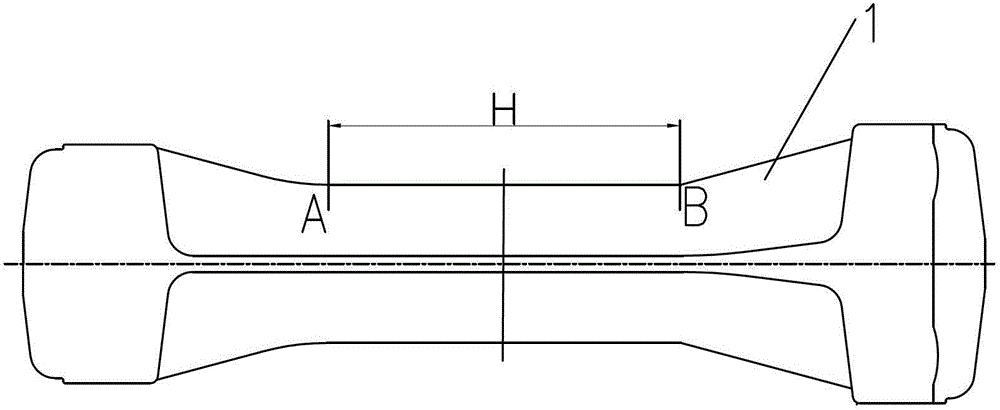
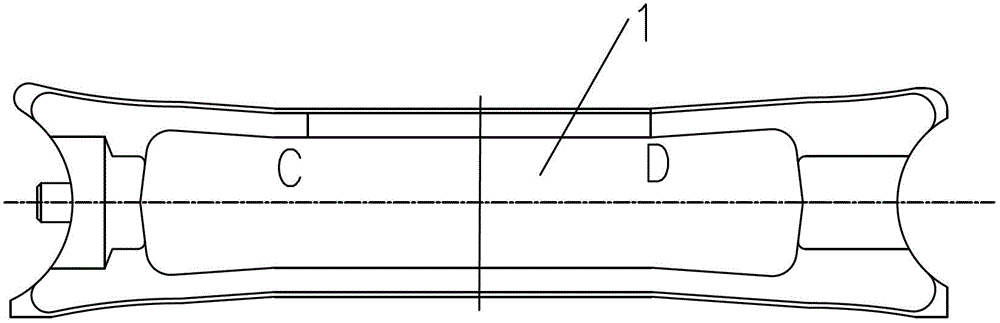
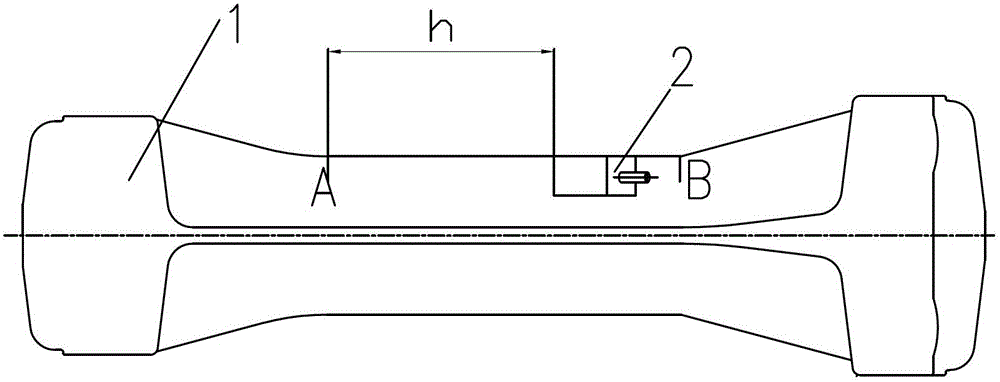
[0013] An ultrasonic surface wave detection method for fatigue cracks of locomotive connecting rods according to the present invention,

[0014] (1) Place the ultrasonic surface wave probe 2 on the connecting rod physical test block 1, and move the ultrasonic surface wave probe 2 back and forth to test the artificial defects on the connecting rod physical test block 1, and connect it with the ultrasonic surface wave probe 2 The ultrasonic detector receives the reflected echo signal of the surface wave, displays the reflected echo signal on the display screen of the ultrasonic detector, and performs horizontal ranging calibration and the starting point of the reflected echo amplitude for the ultrasonic detector and the ultrasonic surface wave probe Sensitivity Calibration.

[0015] See figure 1 , 2 As shown, the artificial defect of the connecting rod physical test block 1 of the present invention is a notch. There are at least two notches on each side of the rod reinforceme...


PUM


Abstract

The invention relates to an ultrasonic surface wave detection method for detecting fatigue crack of an engine connecting rod, comprising the following steps of: placing an ultrasonic surface wave probe on a connecting rod test block for artificial defect test, receiving a reflection echo signal of a surface wave by a supersonic reflectoscope, displaying the reflection echo signal on a display screen of the supersonic reflectoscope, carrying out horizontal range finding calibration on the supersonic reflectoscope and the ultrasonic surface acoustic wave probe and initial sensitivity calibration of reflection echo amplitude, cleaning and planishing two side surfaces of the connecting rod rib, placing the ultrasonic surface acoustic wave probe on the side surfaces of the connecting rod rib and moving back and forth, and determining that there is a connecting rod crack defect and the position of the connecting rod has crack when the reflection echo amplitude of the surface wave is 6dB greater than the initial sensitivity calibration. According to the invention, the fatigue crack of the connecting rod can be detected without demounting the connecting rod from the engine. The method provided by the invention has advantages of low detection cost and high efficiency, and can be used to effectively detect early fatigue crack of the engine connecting rod and guarantee operational safety of the engine more reliably.

Description

technical field [0001] The invention relates to an ultrasonic surface wave detection method for fatigue cracks of a locomotive connecting rod, belonging to the technical field of nondestructive detection of connecting rods. Background technique [0002] With the large-scale speed increase of my country's railways, the running speed and load capacity of locomotives have been greatly improved, effectively solving the problem of railway transportation. However, with the increase of locomotive speed and load capacity, the traction force of the locomotive will also be greatly increased. As a key component of the energy transfer unit in the locomotive, the connecting rod in the diesel engine body is subjected to high-frequency vibration during its operation. The effect of alternating tension and pressure is easy to produce fatigue cracks in the stress concentration part of the shaft. However, if the fatigue cracks on the surface of the connecting rod are not discovered and detect...

Claims


Application Information

Patent Timeline
Patent Type & Authority Patents(China)
IPC IPC(8): G01N29/04
Inventor 万升云姚荣文章文显刘仕远任好娟卢东磊郑小康
Owner CRRC QISHUYAN INSTITUTE CO LTD
Why Eureka
Try Eureka