
Light source device and projector

A technology of a light source device and a projector, which is applied to lighting devices, projection devices, light source fixing, etc., can solve the problems of increasing the manufacturing cost of the projector casing, and achieve the effects of simple structure, low manufacturing cost, and high brightness

Active Publication Date: 2012-10-17
CASIO COMPUTER CO LTD
View PDF5 Cites 14 Cited by
  • Summary
  • Abstract
  • Description
  • Claims
  • Application Information

AI Technical Summary

Problems solved by technology

Therefore, there are cases where the manufacturing cost and the projector cabinet are increased.

Method used


Image

  • Light source device and projector
  • Light source device and projector
  • Light source device and projector

Examples


Embodiment Construction

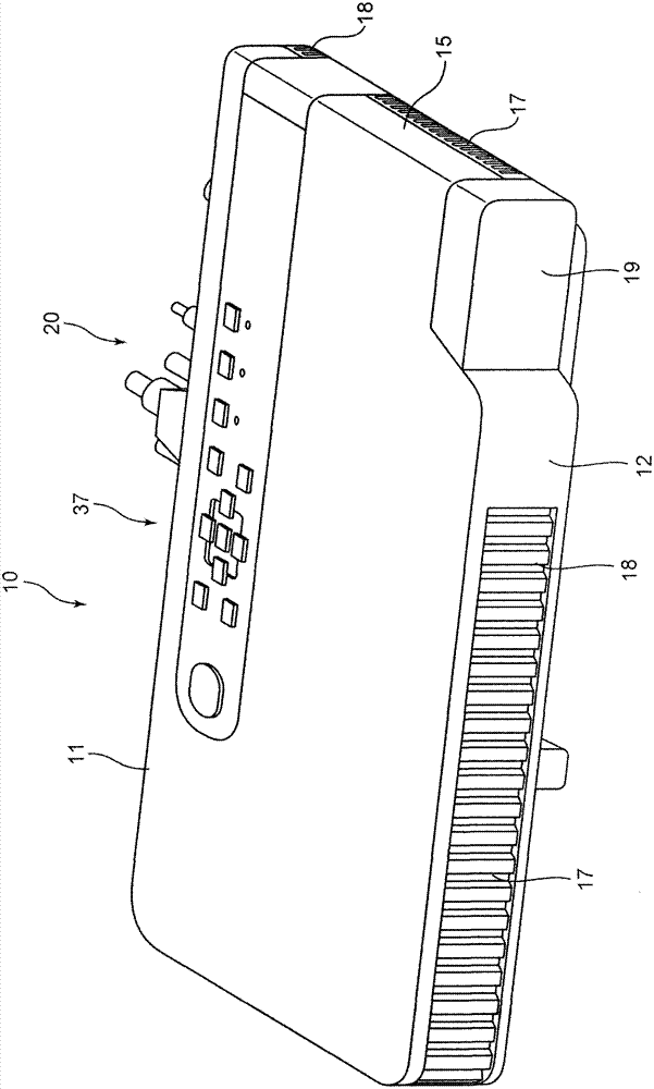
[0024] Hereinafter, embodiments for implementing the present invention will be described. figure 1 It is a perspective view of the appearance of the projector 10. In addition, in the present embodiment, the left and right of the projector 10 indicate the left and right directions with respect to the projection direction, and the front and rear of the projector 10 indicate the front and rear directions with respect to the screen side direction of the projector 10 and the traveling direction of the light beam.

[0025] And, the projector 10 is like figure 1 As shown, it has a substantially rectangular parallelepiped shape. On the side of the front panel 12 constituting the front side plate of the projector cabinet, there is a lens cover 19 covering the projection port, and the front panel 12 is provided with a plurality of suction holes 18. In addition, it includes an Ir receiver (not shown) that receives control signals from the remote controller.

[0026] In addition, the top pan...


PUM


Abstract

A light source device includes: light sources arranged in a plane; collimator lenses disposed in the vicinities of corresponding each of the light sources, each of the collimator lenses collimating a light beam emitted from the corresponding light source, and a holder that holds the light sources and the collimator lenses. The holder holds the light sources and the collimator lenses so that optical axes of the collimator lenses are parallel with the optical axes of the light sources and respectively shifted relative to the latter by shift lengths that are set so that light beams emitted from the light sources via the collimator lenses are focused on a certain region of an illumination subject body. The light beams emitted from the light sources are refracted by the collimator lenses and focused on the certain region.

Description

[0001] This application is based on the application date of March 31, 2011, the application number is 2011-079371, and the priority of the application is claimed. The disclosure of the description, claims, drawings and abstract is here as a whole Cite for reference. Technical field [0002] The embodiment of the present invention relates to a light source device and a projector. Background technique [0003] Nowadays, as an image projection device that projects a screen of a personal computer, a video image, and an image of image data stored in a memory card, etc., on a screen, a data projector is often used. This projector condenses the light emitted from the light source on a micromirror display element called DMD (Digital Micromirror Device) or a liquid crystal panel, and displays a color image on the screen. [0004] Among such projectors, high-intensity discharge lamps have become the mainstream as the light source. However, in recent years, the development of various projecto...

Claims


Application Information

Patent Timeline
IPC IPC(8): G03B21/20G03B21/14F21V14/06F21V13/00
CPCG03B21/204G03B21/208G03B21/2013
Inventor 黑崎秀将
Owner CASIO COMPUTER CO LTD
Learn More