Pressure control device

A technology of pressure control and housing, applied in the direction of electrical components, electric switches, circuits, etc., can solve the problems of affecting the working life of pressure switches, slow contact closure and disconnection, contact closure and disconnection, etc., to reduce sparks and arcs The effect of producing, improving working life and increasing reliability

Inactive Publication Date: 2012-10-17
南京荣欣化工有限公司
View PDF4 Cites 2 Cited by
  • Summary
  • Abstract
  • Description
  • Claims
  • Application Information

AI Technical Summary

Problems solved by technology

Flat diaphragm and corrugated diaphragm pressure control switches are easy to be made into smaller volumes, but the closing and opening of the contacts is relatively slow, which is prone to generate large sparks and arcs, ablate the contacts, and then affect the work of the pressure switch Life, and when the pressure value changes near the rated starting pressure value, the contact will appear repeatedly closed and disconnected

Method used


Image

  • Pressure control device

Examples


Embodiment 1

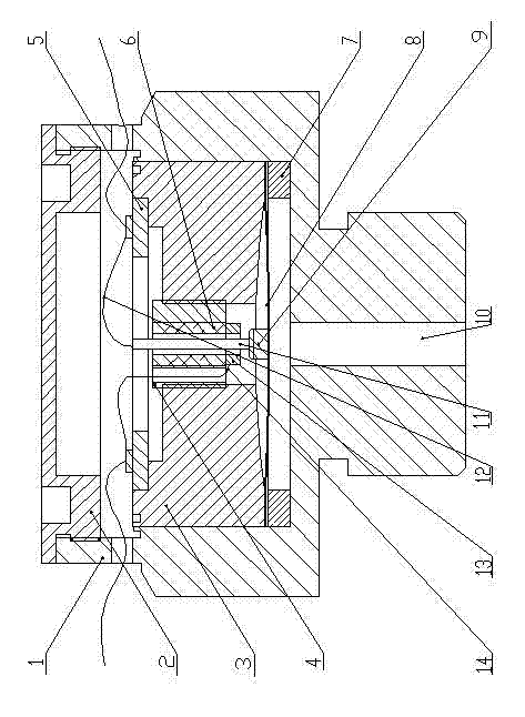
[0017] as attached figure 1 As shown: the pressure control device of the present invention includes: a housing 1 and an upper cover 2 connected to the housing, a fixing seat 3 with a circular arc contact surface is installed in the housing, and an adjustment terminal is installed on the fixing seat 4 and an adapter plate 5, a set of jumping diaphragms 8 are installed on the housing, a ceramic ring 6 is installed in the middle of the adjustment terminal, a backing ring 7 is installed in the housing, and a jumping ring is installed on the backing ring Diaphragm, the lower electrode 9 is installed on the jumping diaphragm, the copper wire 11 of the lower electrode passes through the central hole of the adjustment terminal, and the wire 12 is drawn out from the upper end of the copper wire to connect to the transfer The upper electrode 13 is installed under the adjustment terminal, and the lead wire 14 of the upper electrode passes through the side hole of the adjustment terminal ...

Embodiment 2

[0019] In the pressure control device, the bottom surface of the fixing seat has a circular arc structure.

Embodiment 3

[0021] In the pressure control device, there is an air inlet or liquid inlet hole 10 under the housing.

[0022] work process:

[0023] The measured gas or liquid enters the pressure control switch from the inlet (liquid) hole, and the pressure acts on the convex surface of the jumping diaphragm. When the pressure value reaches (exceeds) the jumping critical point of the jumping diaphragm, the jumping diaphragm generates a jumping, that is, the original convex surface is instantly depressed, the original concave surface is raised, and the lower electrode is displaced with the deformation of the jumping diaphragm, and the upper electrode The contact conducts, and the switch is closed instantaneously; when the pressure value falls back (lower) to the rebound critical point of the jumping diaphragm, the jumping diaphragm rebounds, and the switch is disconnected instantaneously.


PUM


Abstract

The invention provides a pressure control device. The pressure control device comprises a shell (1) and an upper cover (2) which is connected with the shell (1), wherein a fixed base (3) with an arc contact surface is installed in the shell, adjusting terminals (4) and an adapter plate (5) are installed on the fixed base, a group of jump diaphragms 8 are installed on the shell, ceramic rings (6) are arranged among the adjusting terminals, a backing ring (7) is installed in the shell, the jump diaphragms are arranged on the backing ring, lower electrodes (9) are installed on the jump diaphragms, the copper wires (11) of the lower electrodes penetrate through the central holes of the adjusting terminals, and lead out wires (12) from the upper ends of the copper wires to be connected with the adapter plate, upper electrodes (13) are installed below the adjusting terminals, and the leading-out wires (14) of the upper electrodes penetrate through the side holes of the adjusting terminals to be connected with the adapter plate. The pressure control device is used for gas or liquid supply pressure control.

Description

technical field [0001] The invention relates to a chemical reaction control device, in particular to a pressure control device. Background technique [0002] In the chemical production process, pressure control is often used in liquid or gas pipelines. At present, the mechanical pressure control switches developed and produced at home and abroad are flat diaphragm type, corrugated diaphragm type, bellows type, bellows type and rubber type. model. Among them, the bellows type and the bellows type are large in volume. Although the pressure control switch of the rubber membrane type can be made into a smaller volume, the control error is large, and it is difficult to withstand low and high temperatures. Flat diaphragm and corrugated diaphragm pressure control switches are easy to be made into smaller volumes, but the closing and opening of the contacts is relatively slow, which is prone to generate large sparks and arcs, ablate the contacts, and then affect the work of the...

Claims


Application Information

Patent Timeline
Patent Type & Authority Applications(China)
IPC IPC(8): H01H35/34
Inventor 林毓勇王海霞李刚徐彬彬刘春
Owner 南京荣欣化工有限公司
Why Eureka
Try Eureka