Chemical mechanical polishing method

A technology of chemical machinery and grinding methods, which is applied in the fields of electrical components, semiconductor/solid-state device manufacturing, circuits, etc., can solve the problems of reducing the grinding rate, and achieve the effect of accelerating the grinding rate and improving the grinding efficiency

Inactive Publication Date: 2012-10-17
NAN YA TECH
View PDF5 Cites 5 Cited by
  • Summary
  • Abstract
  • Description
  • Claims
  • Application Information

AI Technical Summary

Problems solved by technology

[0004] However, when the substrate is chemically mechanically polished using a hydrophobic polishing pad, by-products such as surfactants will accumulate on the hydrophobic polishing pad, reducing the polishing rate.

Method used


Image

  • Chemical mechanical polishing method

Examples


Embodiment Construction

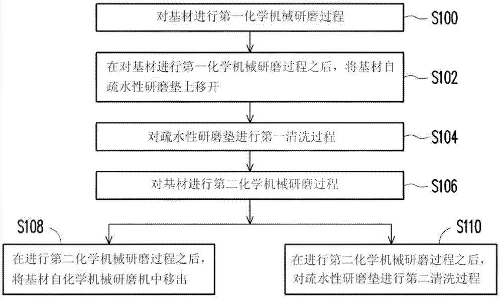
[0021] figure 1 It is a flowchart of a chemical mechanical polishing method according to an embodiment of the present invention.

[0022] The chemical mechanical polishing method disclosed in this embodiment is described by using a hydrophobic polishing pad to polish a substrate in a chemical mechanical polishing machine as an example. Wherein, the substrate is, for example, a silicon wafer, but it is not intended to limit the scope of the present invention.

[0023] Firstly, step S100 is performed to perform a first chemical mechanical polishing process on the base material. That is, the substrate is fed into a chemical mechanical polisher and polished with a hydrophobic polishing pad to remove part of the substrate. The operation time of the first chemical mechanical polishing process is, for example, less than 120 seconds.

[0024] Next, step S102 can be optionally performed. After the substrate is subjected to the first chemical mechanical polishing process, the substra...


PUM


Abstract

A chemical mechanical polishing (CMP) method is provided. The method is capable of polishing a substrate in a CMP apparatus by using a hydrophobic polishing pad and includes following steps. A first CMP process is performed to the substrate. A first cleaning process is performed to the hydrophobic polishing pad. A second CMP process is performed to the substrate, wherein the first CMP process, the first cleaning process and the second CMP process are performed in sequence. The invention enables the polishing efficiency to be improved effectively when the hydrophobic polishing pad is used.

Description

technical field [0001] The invention relates to a chemical mechanical grinding method, in particular to a segmented chemical mechanical grinding method. Background technique [0002] As the size of components continues to shrink, the resolution of lithography exposure increases relatively, and with the reduction of exposure depth of field, the requirements for the level of chip surface fluctuations are more stringent. Therefore, when entering the deep sub-micron process, the planarization of the chip depends on the chemical mechanical polishing process. Its unique anisotropic grinding properties can also be applied to the vertical And the production of the mosaic structure of the horizontal metal interconnection machine, the production of shallow trench isolation of components in the front-end process and the production of advanced components, the planarization of micro-electromechanical systems and the production of flat-panel displays, etc. [0003] Chemical mechanical po...

Claims


Application Information

Patent Timeline
Patent Type & Authority Applications(China)
IPC IPC(8): H01L21/321H01L21/30
CPCH01L21/3212H01L21/31053
Inventor 廖建茂陈逸男刘献文
Owner NAN YA TECH
Why Eureka
Try Eureka