Linear motor
A linear motor and electric motor technology, applied in the direction of electric components, electrical components, electromechanical devices, etc., can solve the problems of high temperature of the moving sub-board, burnout, and the inability of the linear motor to work stably and efficiently, so as to improve the life of the motor and improve the working efficiency. quality effect
- Summary
- Abstract
- Description
- Claims
- Application Information
AI Technical Summary
Problems solved by technology
Method used
Image

Examples
Embodiment Construction
[0028] In order to make the technical problems, technical solutions and advantages to be solved by the present invention clearer, the following will describe in detail with reference to the drawings and specific embodiments.
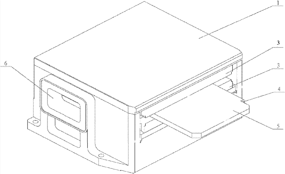
[0029] An embodiment of the present invention provides a linear motor, such as figure 1 As shown, including motor stator 3 and motor mover board 5:
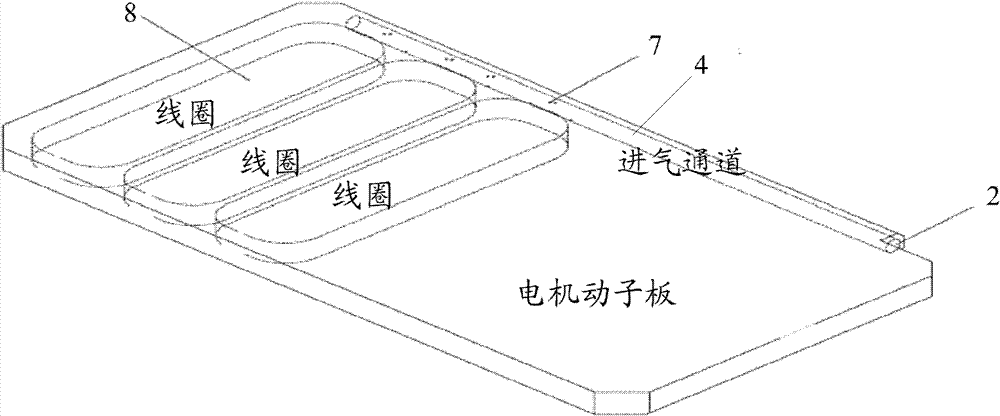
[0030] The motor sub-plate 5 is provided with an air intake passage 4;
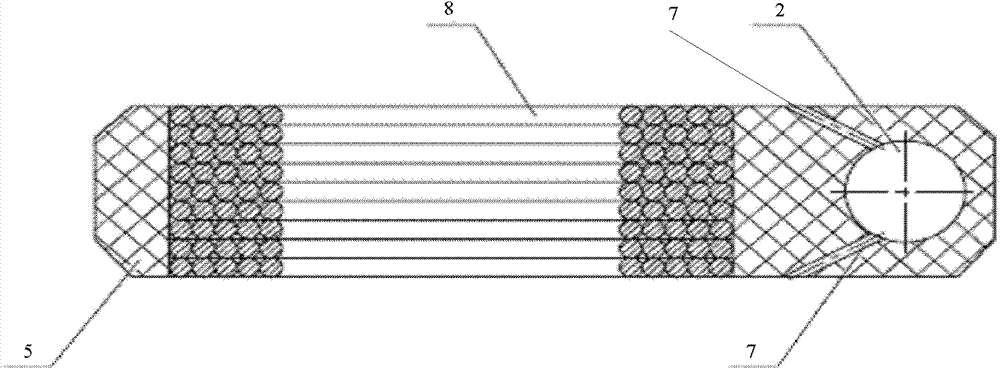
[0031] The first plate surface and the second plate surface of the motor rotor plate 5 are respectively provided with air outlet holes 7 communicating with the air intake passage 4;
[0032] There is a ventilation channel between the motor stator 3 and the motor rotor plate 5, and the air outlet hole 7 communicates with the ventilation channel.
[0033] Applying the provided technical solution, the motor sub-plate 5 will generate a large amount of heat when it is in the state of high-speed and high-frequency movement during the worki...
PUM
 Abstract
Description
Claims
Application Information
 - Generate Ideas
- Intellectual Property
- Life Sciences
- Materials
- Tech Scout
- Unparalleled Data Quality
- Higher Quality Content
- 60% Fewer Hallucinations
Browse by: Latest US Patents, China's latest patents, Technical Efficacy Thesaurus, Application Domain, Technology Topic, Popular Technical Reports.
© 2025 PatSnap. All rights reserved.Legal|Privacy policy|Modern Slavery Act Transparency Statement|Sitemap|About US| Contact US: help@patsnap.com