
Tail pulley chain device for hot ore chain scraper conveyor

A technology of chain-plate conveyor and tail wheel, which is applied in the direction of conveyor, transportation and packaging, etc. It can solve the problems of high cost, stuck chain, climbing chain, etc., and achieve the effect of low cost, simple and reliable structure, and simple structure

Inactive Publication Date: 2012-10-24
SHANDONG LAIWU COAL MINING MACHINERY
View PDF7 Cites 2 Cited by
  • Summary
  • Abstract
  • Description
  • Claims
  • Application Information

AI Technical Summary

Problems solved by technology

The cost of the tail wheel chain device for the traditional chain-plate conveyor is high, and it is inconvenient to fill the oil cup on the hub of the tail wheel.

Method used


Image

  • Tail pulley chain device for hot ore chain scraper conveyor
  • Tail pulley chain device for hot ore chain scraper conveyor

Examples


Embodiment Construction

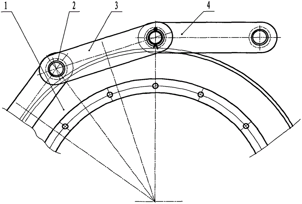
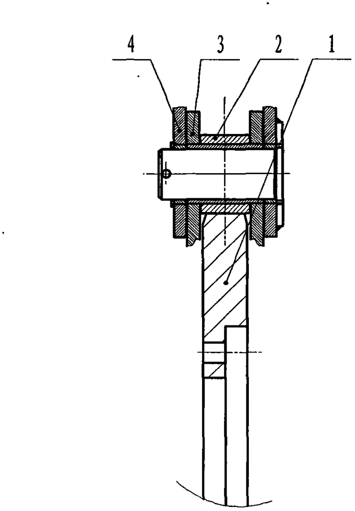
[0011] The chain-plate conveyor is generally installed on a slope with a certain inclination angle. The motor reducer drives the head wheel to rotate, and then the head wheel drives the chain, and the chain drives the tail wheel. The hopper is installed on the chain, and the hopper and the chain move together. The tail of the chain plate conveyor is used for the hopper to turn and carry the hopper at the turn at the tail. Part 1: There are no teeth on the sprocket of the tail wheel. At the turn at the tail, the outer circle of the sprocket of the tail wheel is tangent to the outer circle of the roller on the chain, so that the distance between the center of the sprocket and the roller remains unchanged. The sprocket of the tail wheel is on the chain Between the chain plates, the chain is prevented from moving along the axis of the tail wheel shaft, which ensures that the chain plate conveyor is used to turn the hopper at the tail and carry the hopper; the hubs and shafts at bot...


PUM


Abstract

The invention discloses a tail pulley chain device for a hot ore chain scraper conveyor and belongs to devices in the field of metallurgy. The tail pulley chain device is used for turning at a turning position on the tail portion of a hopper and for bearing the hopper, is mainly used for hot ore chain scraper conveyors of sintering plants in steel and iron enterprises and is suitable for the hot ore chain scraper conveyors of other industries. The tail pulley chain device is structurally characterized in that chain wheels of a tail pulley are toothless, hubs and shafts at two ends of the tail pulley are all fixed, and no rib plate is arranged between chain plates on the chain wheels. The chain wheels of the tail pulley are toothless so that in turning of the tail portion, the excircles on the chain wheels of the tail pulley are tangent with the excircle of an idler wheel on a chain, the distance between centers of the chain wheels and the idler wheel is constant, and the chain wheels of the tail pulley isare arranged between the chain and the chain plates to prevent the chain from moving along the axis direction of a tail pulley shaft. The hubs and the shafts at two ends of the tail pulley are all fixed, the chain wheels on the tail pulley are toothless, the chain wheels at two ends of the tail pulley are not synchronous, copper bushes between the hubs and the shafts are reduced, oil cups are correspondingly reduced, and the structure of the tail pulley is easier. No rib plate is arranged between the chain plates on the chain, and manufacturing of the chain plates is easier.

Description

Technical field [0001] The tail wheel chain device of the present invention is a chain plate conveyor used for turning the hopper at the tail turning and carrying the hopper. It is a key component of the chain plate conveyor. Its operation is mainly driven by the head wheel. Chain, The chain drives the tail wheel to complete the process. It is mainly used for hot ore chain plate conveyors in sintering plants of iron and steel enterprises, and can also be applied to hot ore chain plate conveyors in other industries. It belongs to the equipment in the field of metallurgy. Background technique [0002] The structure of the traditional tail wheel chain device for chain-plate conveyors is mainly as follows: there are teeth on the sprocket of the tail wheel, the hub and shaft at one end of the tail wheel are fixed, and the hub and shaft at the other end of the tail wheel are not fixed, between the hub and the shaft There are copper sleeves, there are oil holes on the hub and the c...

Claims


Application Information

Patent Timeline
Patent Type & Authority Applications(China)
IPC IPC(8): B65G17/38
Inventor 李伟庞素平张超李彬亓玉王丰庆李宝华朱绍峰滕海燕刘霞
Owner SHANDONG LAIWU COAL MINING MACHINERY
Learn More