
Shale gas stimulation method and shale gas stimulation equipment

A technology for shale gas and shale gas wells, which is used in earth-moving drilling, isolation devices, and production fluids, etc., and can solve problems such as the inability to greatly increase the daily gas production, the inability to effectively increase the production of shale gas, and the complex equipment.

Active Publication Date: 2015-11-25
CHINA UNIV OF PETROLEUM (BEIJING)
View PDF6 Cites 2 Cited by
  • Summary
  • Abstract
  • Description
  • Claims
  • Application Information

AI Technical Summary

Problems solved by technology

However, due to the depressurization process in the production well, the CO 2 is injected in the injection well, resulting in CH 4 with CO 2 The competition may not occur at the same time. In addition, the effective time of shale gas production is shortened due to the repeated cycle of boosting and depressurizing, so the daily gas production cannot be greatly increased.
Moreover, this production increase method has complex equipment and extremely high preparation costs, which also make it only in the laboratory research stage
[0006] In summary, none of the existing shale gas stimulation methods can quickly and effectively realize shale gas stimulation, and at the same time, there is no economical and reasonable shale gas stimulation equipment

Method used


Image

  • Shale gas stimulation method and shale gas stimulation equipment
  • Shale gas stimulation method and shale gas stimulation equipment
  • Shale gas stimulation method and shale gas stimulation equipment

Examples


Embodiment 1

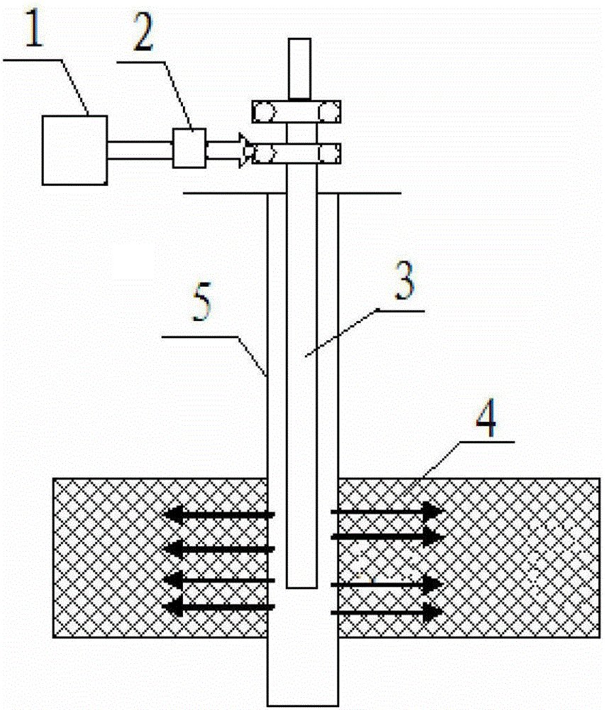
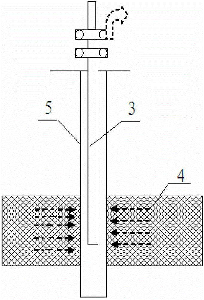
[0037] figure 1 It is a schematic diagram of superheated steam heating in the present invention; figure 2 It is a schematic diagram of superheated steam heating exploitation in the present invention.

[0038]In this embodiment, the shale gas to be exploited is located at a burial depth of about 1000 meters, and the original temperature of the shale layer where the shale gas is located is about 50°C. After a period of normal gas production of shale gas wells, when the daily output of a single well is lower than the industrial development standard (1000 m 3 / day), using the shale gas stimulation method to continue to exploit shale gas, specifically the superheated steam method (also known as superheated steam huff and puff) to exploit shale gas, including the following steps:

[0039] (1) Transport heat energy to the shale layer 4 of the shale gas well, and increase the temperature of the shale layer by driving the transported heat energy to realize heat transfer in the shale...

Embodiment 2

[0044] The difference from Example 1 is that in this example, the superheated steam temperature is 250°C, the steam injection pressure of a single well is 1MPa higher than the shale pore pressure, and the steam injection speed is 10m 3 / h water equivalent superheated steam, so that the dryness of the superheated steam entering the shale layer where the shale gas is located is greater than 60%. The total amount of superheated steam injected is 15 tons of water equivalent steam per meter of shale layer, so that the average temperature of the shale layer within a radius of 50 meters from the shale gas well will increase by 30°C.

[0045] In this example, the temperature of the original formation is about 50°C. After heating, the average temperature of the shale layer within a radius of 50 meters from the bottom of the shale gas well can reach 80°C. At this time, the adsorption capacity of the shale layer is reduced to about 1 / 10 of the original, and the desorption rate is about 1 / ...

Embodiment 3

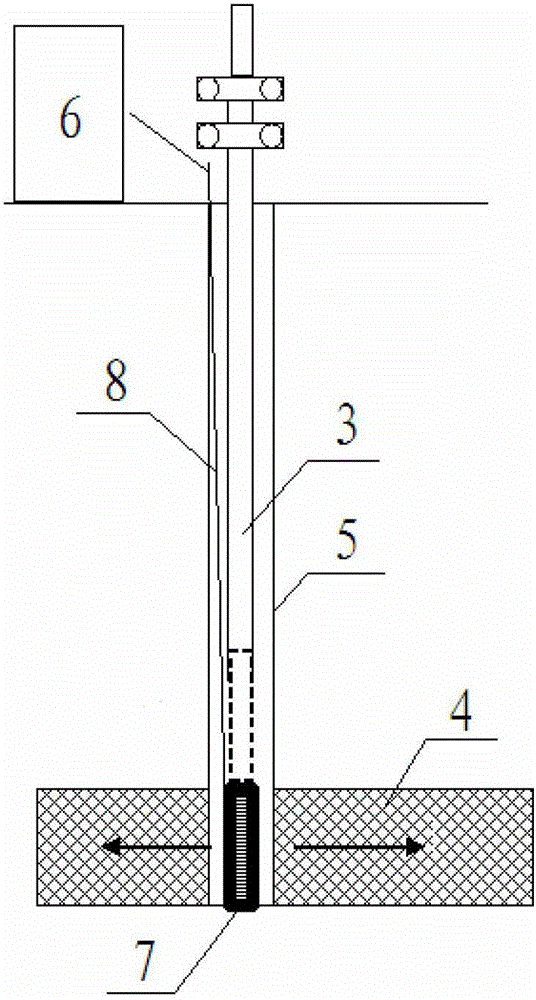
[0047] image 3 It is a schematic diagram of microwave heating of the present invention; Figure 4 It is a schematic diagram of microwave heating mining in the present invention.

[0048] In this embodiment, the shale gas to be exploited is located at a burial depth of about 800 meters in the shale layer, and the original temperature of the shale layer is about 40°C. After a period of normal gas production of shale gas wells, when the daily output of a single well is lower than the industrial development standard (1000 m 3 / day). Using the shale gas stimulation method to continue to exploit shale gas, specifically to exploit shale gas by microwave heating, includes the following steps:

[0049] (1) Transport heat energy to the shale layer 4 of the shale gas well, and increase the temperature of the shale layer by driving the transported heat energy to realize heat transfer in the shale layer 4; specifically, place the microwave generator 7 in the shale layer The shale laye...


PUM


Abstract

The invention provides a shale gas production increasing method and shale gas production increasing equipment. The shale gas production increasing method comprises the following steps of: transmitting heat energy to a shale layer of a shale gas well and raising the temperature of the shale layer by driving transmitted heat energy to realize heat transfer in the shale layer; closing shale gas well for 1-10 days; and opening the shale gas well to exploit gas. The invention also provides two kinds of shale gas production increasing equipment for realizing the shale gas production increasing method. According to the shale gas production increasing method and the shale gas production increasing equipment, the various problems in the conventional shale gas exploitation are solved, the shale gas desorption velocity and the seepage velocity are effectively increased, and further the shale gas yield is improved. The shale gas production increasing method provided by the invention is suitable for shale gas development of straight wells, horizontal wells or multi-branch wells.

Description

technical field [0001] The invention relates to shale gas exploitation technology, in particular to a shale gas stimulation method and shale gas stimulation equipment. Background technique [0002] Shale gas is natural gas that occurs in dark mud shale layers or high-carbon mud shale layers. It can be generated in various stages of organic origin. Part of the natural gas exists in the free phase state (about 50%) in shale layer fractures, Pores in shale layers and other storage spaces, the other part exists in the state of adsorption (about 50%) on the surface of kerogen, clay particles and clay pores. Shale gas is a valuable resource, high-quality energy and chemical raw material, and can be used as a replacement or supplementary energy source for conventional natural gas. [0003] Existing shale gas mining mainly relies on its own desorption. After a period of gas production, the output of shale gas drops sharply, and the effect of shale gas extraction is not ideal. The o...

Claims


Application Information

Patent Timeline
Patent Type & Authority Patents(China)
IPC IPC(8): E21B43/241E21B36/00
Inventor 杨胜来李芳芳章星李敏石魏钱坤孟维伟娄毅
Owner CHINA UNIV OF PETROLEUM (BEIJING)
Learn More