Eureka AIR delivers breakthrough ideas for toughest innovation challenges, trusted by R&D personnel around the world.

Method for designing stiffness of helical spring of combined valve for shock absorbers

A coil spring and stiffness design technology, applied in the direction of shock absorbers, springs, shock absorbers, etc., can solve the problem that it is difficult to meet the requirements of shock absorber design and characteristic simulation modeling, there is no fast and accurate design method, and there is no established Reliable calculation methods and other issues to achieve the effect of avoiding repeated tests and modifications, reducing design and test costs, and accurate and reliable stiffness design values

Inactive Publication Date: 2012-10-24
SHANDONG UNIV OF TECH
View PDF5 Cites 20 Cited by
  • Summary
  • Abstract
  • Description
  • Claims
  • Application Information

AI Technical Summary

Problems solved by technology

Although scholars have done a lot of research on this, they have only established an analytical calculation method for the deformation of the valve plate under uniform pressure. For the deformation of the valve plate under the force of the spring, there is still no reliable calculation method. Finite element software for numerical simulation through modeling
Because the finite element numerical simulation method does not provide analytical calculation formulas, it is difficult to meet the requirements of actual shock absorber design and characteristic simulation modeling
Therefore, at present, there is no fast and accurate design method for the stiffness of the coil spring of the composite valve of the automobile shock absorber, which cannot meet the requirements of fast and accurate design of the modern automobile shock absorber. It is necessary to establish a design method for the stiffness of the coil spring of the composite valve of the automobile shock absorber

Method used


Image

  • Method for designing stiffness of helical spring of combined valve for shock absorbers
  • Method for designing stiffness of helical spring of combined valve for shock absorbers
  • Method for designing stiffness of helical spring of combined valve for shock absorbers

Examples


Embodiment Construction

[0021] The present invention will be further described in detail through an embodiment below.

[0022] In order to meet the characteristic design requirements of the shock absorber, an automobile shock absorber adopts a compound throttle valve composed of a coil spring and a throttle valve plate. The inner circle radius of the throttle plate of the compound valve is =5.0mm; and valve port position radius =8.0mm; outer circle radius =8.5mm; Throttle valve thickness =0.15mm; the modulus of elasticity of the throttle plate material and Poisson's ratio , coil spring precompression =10.0mm; the pre-deformation of the valve plate required by the characteristics of the shock absorber =0.04mm.

[0023] The specific steps of the method for calculating the deformation of the throttle plate of the cylindrical hydraulic shock absorber under the force of the spring provided by the embodiment of the present invention are as follows:

[0024] (1) According to the radius of the...


PUM


Abstract

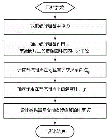
The invention relates to a method for designing the stiffness of a helical spring of a combined valve for shock absorbers, which belongs to the field of shock absorbers. The method is characterized by comprising the following steps: (1) according to the radius of the inner circle of a throttling valve sheet of the combined valve for shock absorbers and the radius at the position of a valve port, selecting an intermediate diameter of the helical spring; (2) determining the inside and outside radii of a contact circular ring (acted on the throttling valve sheet) of the helical spring; (3) calculating the deformation coefficient of the throttling valve sheet at the position of the valve port; (4) determining the spring pressure acted on the throttling valve sheet; and (5) determining the stiffness of the helical spring of the combined valve for shock absorbers. According to the invention, as an analytical design method is adopted, the stiffness design value is more accurate and reliable, thereby avoiding the operations of repeated testing and modifying, lowering the design cost of a shock absorber, and improving the development cycle of the shock absorber; and by using the analytical design method, the fast and accurate design requirements of helical springs of combined valves for shock absorbers for automobiles can be satisfied.

Description

technical field [0001] The invention relates to a shock absorber, in particular to a method for designing the rigidity of a helical spring of a compound valve composed of a throttle plate and a helical spring for an automobile shock absorber. Background technique [0002] In order to meet the design requirements of the shock absorber, some automobile shock absorbers use a composite throttle valve composed of a coil spring and a throttle valve plate. The damping characteristics are mainly determined by the parameters of the shock absorber valve system. Among them, the coil spring Stiffness plays a key role in the characteristics of the shock absorber. At present, there is no accurate and reliable design method for the design of shock absorber valve system parameters at home and abroad. Most of them use experience to first determine a stiffness value of the coil spring, and then after repeated tests and modifications, finally determine the design stiffness. The main reason is...

Claims


Application Information

Patent Timeline
IPC IPC(8): F16F1/00F16F9/34
Inventor 周长城赵雷雷刘小亭
Owner SHANDONG UNIV OF TECH
Why Eureka
Eureka Blog
Learn More