Energy-saving device capable of preheating coal gas on ceramic kiln

A ceramic kiln and gas technology, applied in the field of ceramic kiln, can solve the problems of unfavorable energy saving and consumption reduction, affecting the firing quality of ceramic products, and large axial flow of cold gas

Active Publication Date: 2012-10-24
梁嘉承
View PDF5 Cites 2 Cited by
  • Summary
  • Abstract
  • Description
  • Claims
  • Application Information

AI Technical Summary

Problems solved by technology

[0002] In the high-temperature firing zone of the ceramic kiln, the cold gas at 30°C is generally directly input for combustion and heating. Since the combustion of the cold gas is not sufficient, it will cause a large loss and waste of heat energy, which is not conducive to energy saving and consumption reduction. Moreover, cold The axial flow generated by the gas is relatively large, which will cause a certain temperature difference in each area of ​​the furnace, thus affecting the firing quality of ceramic products, which needs to be improved

Method used


Image

  • Energy-saving device capable of preheating coal gas on ceramic kiln
  • Energy-saving device capable of preheating coal gas on ceramic kiln
  • Energy-saving device capable of preheating coal gas on ceramic kiln

Examples


Embodiment 1

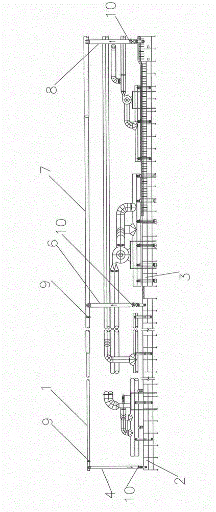
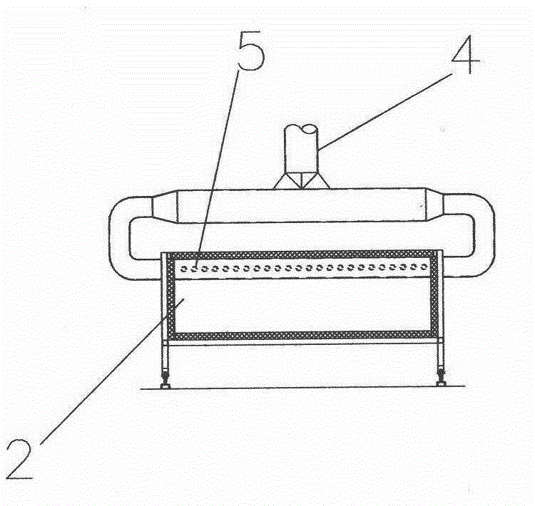
[0015] see Figure 1-Figure 4 , providing an energy-saving device capable of preheating gas on a ceramic kiln. The ceramic kiln includes a single-layer drying area and a single-layer preheating area in sequence. A cold gas pipe 1 extending transversely is arranged above the two, and the drying area and the preheating zone respectively include several drying boxes 2 and preheating boxes 3 extending transversely, above the drying box 2 at the beginning of the drying zone, there is a cold gas inlet main pipe 4, which is vertically connected with the cold gas pipe 1, The lower part traverses into the top position of the drying box 2 at the beginning of the drying area, and the intake manifold 4 is located on a section of each starting drying box 2, and is vertically connected with 24 gas preheating pipes 5, and all preheating pipes 5 are all along the direction from the drying area to the preheating area, passing through several drying boxes 2 and preheating boxes 3 in sequence; a...

Embodiment 2

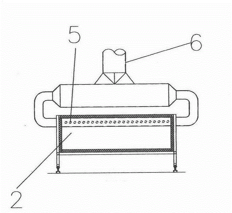
[0018] see Figure 5-Figure 6 , the main difference with Embodiment 1 is only that the drying area of ​​the ceramic kiln is a two-layer drying area, and the air intake main pipe 4 of the cold gas is laterally branched into the top position of the drying box 2 at the beginning of each layer of the two-layer drying area. , the lower part of the primary output pipe 6 is connected to several preheating pipes 5 passing through the drying oven 2 at the end of each layer of the two-layer drying zone. The structure and realized functions of other aspects are completely consistent with the first embodiment.


PUM


Abstract

The invention discloses an energy-saving device capable of preheating coal gas on a ceramic kiln. The ceramic kiln sequentially comprises a single-layer or multilayer drying area and a single-layer preheating area. A cold coal gas pipe which extends transversely is arranged above the single-layer or multilayer drying area and the single-layer preheating area. A gas inlet manifold for cold coal gas is arranged above drying boxes at the head of the single-layer or multilayer drying area and is perpendicularly connected with the cold coal gas pipe. The lower part of the gas inlet manifold transversely enters the internal top of a drying box at the head of the single-layer drying area, or transverse branches of the gas inlet manifold enter internal tops of drying boxes at the head of each layer of the multilayer drying area. A plurality of coal gas preheating pipes are perpendicularly arranged at all sections of the gas inlet manifold in each initial drying box. A primary output pipe for preheated coal gas is arranged above drying boxes at the tail of the single-layer or multilayer drying area. A secondary output pipe for the preheated coal gas is arranged above a drying box at one position of the preheating area and is perpendicularly connected with an output manifold. The lower part of the secondary output pipe is connected with the preheating pipes which enter the preheating box at the position. By adopting the structure, a good energy-saving effect can be realized and the sintering quality of ceramic products can be effectively improved.

Description

technical field [0001] The invention relates to a ceramic kiln, in particular to an energy-saving device capable of preheating coal gas on the ceramic kiln. Background technique [0002] In the high-temperature firing zone of the ceramic kiln, the cold gas at 30°C is generally directly input for combustion and heating. Since the combustion of the cold gas is not sufficient, it will cause a large loss and waste of heat energy, which is not conducive to energy saving and consumption reduction. Moreover, cold The axial flow generated by the gas is relatively large, which will cause a certain temperature difference in each area of ​​the furnace, thereby affecting the firing quality of ceramic products, which needs to be improved. Contents of the invention [0003] The technical problem to be solved by the present invention is to provide an energy-saving device capable of preheating gas on a ceramic kiln, which can achieve a good energy-saving effect and effectively improve pro...

Claims


Application Information

Patent Timeline
Patent Type & Authority Applications(China)
IPC IPC(8): F23D14/66
CPCY02E20/34
Inventor 梁嘉键
Owner 梁嘉承
Why Eureka
Try Eureka