Optical fiber coiling device

An optical fiber coiling and optical fiber technology, which is applied in the field of optical fiber devices, can solve the problems of small bending radius, deterioration of laser performance, and brittle fiber texture, and achieve the effect of reducing space.

Inactive Publication Date: 2012-10-24
BEIJING GK LASER TECH
View PDF3 Cites 8 Cited by
  • Summary
  • Abstract
  • Description
  • Claims
  • Application Information

AI Technical Summary

Problems solved by technology

Such a long optical fiber must be coiled on the corresponding device, but the optical fiber is brittle and has a relatively small bending radius, so the optical fiber is not easy to coil
Moreover, the pump light will generate heat during the transmission and oscillation process in the fiber, so it is difficult to dissipate the heat when the fibers are coiled together, resulting in deterioration of laser performance, especially for high-power fiber lasers, the heat dissipation problem is even more serious

Method used


Image

  • Optical fiber coiling device
  • Optical fiber coiling device
  • Optical fiber coiling device

Examples


Embodiment Construction

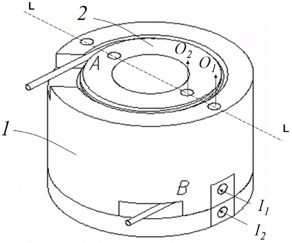
[0025] According to one embodiment of the present invention, an optical fiber coiling device is provided, the three-dimensional structure of which is as follows figure 1 As shown, the optical fiber coiling device includes an inner cylinder 2 and an outer cylinder 1 .

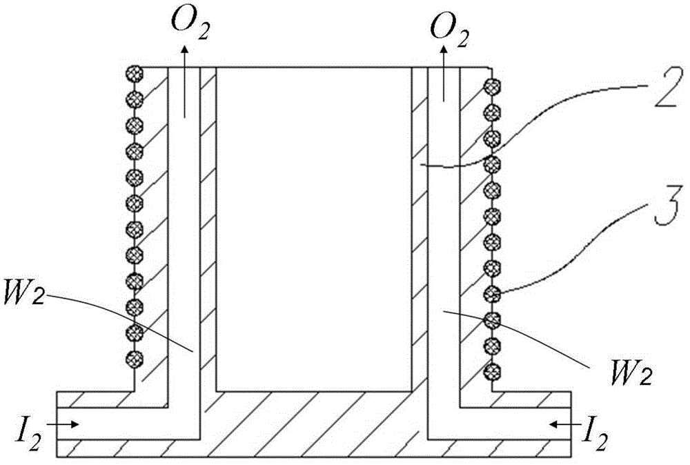
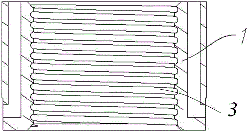
[0026] Wherein the structure of inner cylinder 2 is as figure 2 As shown, it is cylindrical and made of metal material. There is a spiral groove on its outer cylindrical surface for accommodating the optical fiber 3, wherein the cross section of the spiral groove is semicircular, and its diameter is the same as that of the optical fiber. 3 have the same diameter, the three-dimensional view of the structure of the inner tube 2 after the optical fiber 3 is accommodated is as follows image 3 as shown, image 3 It is a schematic cross-sectional view of the outer cylinder after being cut. It can be seen from the figure that the optical fiber 3 is accommodated in the semicircular groove on the inner cylinder, so t...


PUM


Abstract

The invention provides an optical fiber coiling device. The optical fiber coiling device comprises an inner barrel, an outer barrel, wherein the inner barrel is provided with a cylindrical outer surface, a spiral first groove is arranged on the outer surface, a water-cooling channel is further arranged in the inner barrel, the outer barrel is provided with a cylindrical inner surface, a spiral second groove is arranged on the inner surface, and a water-cooling channel is further arranged in the outer barrel. The outer barrel is covered outside the inner barrel, and the position of the first groove and the position of the second groove correspond to each other and are combined with each other to accommodate optical fibers.

Description

technical field [0001] The invention relates to an optical fiber coiling device, in particular to a device for coiling an optical fiber in a high-power optical fiber laser. Background technique [0002] As a representative of the third-generation laser technology, fiber lasers are being used more and more widely. The length of the optical fiber in the fiber laser is generally tens of meters to tens of meters, and the pump light is transmitted and oscillated in the optical fiber until the laser is output. Such a long optical fiber must be coiled on the corresponding device, but the optical fiber is brittle and has a relatively small bending radius, so the optical fiber is not easy to coil. Moreover, the pump light will generate heat during the transmission and oscillation process in the fiber, so it is difficult to dissipate the heat when the fibers are coiled together, resulting in deterioration of laser performance, especially for high-power fiber lasers, the heat dissipat...

Claims


Application Information

Patent Timeline
Patent Type & Authority Applications(China)
IPC IPC(8): H01S3/042
Inventor 王鹏樊仲维石朝辉王培峰闫晓超
Owner BEIJING GK LASER TECH
Why Eureka
Try Eureka