Embedded permanent magnet electric motor
A permanent magnet and motor technology, applied in synchronous motors with stationary armatures and rotating magnets, electric components, magnetic circuit rotating parts, etc., can solve the problem of large coil inductance, inability to obtain high output, and difficulty in winding stator coils. Winding and other problems, to achieve the effect of preventing magnetic flux drop, preventing thermal demagnetization, and easy winding
- Summary
- Abstract
- Description
- Claims
- Application Information
AI Technical Summary
Problems solved by technology
Method used
Image

Examples
Embodiment approach 1
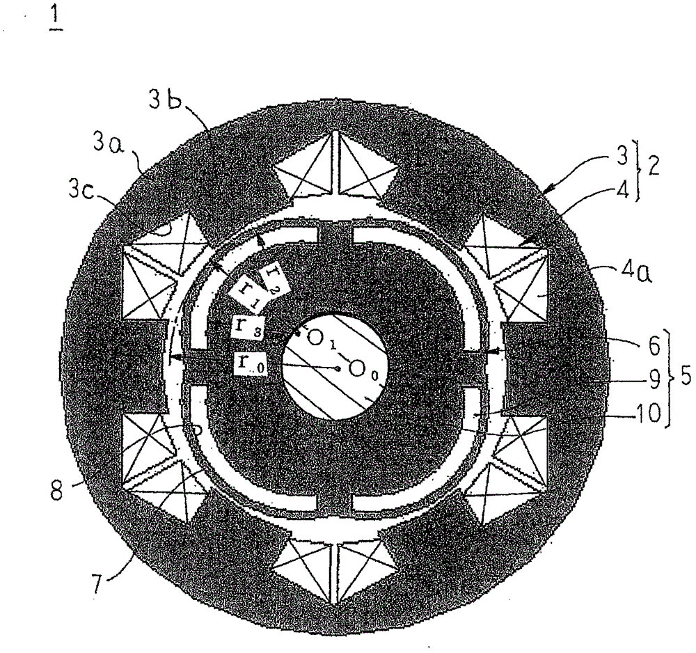
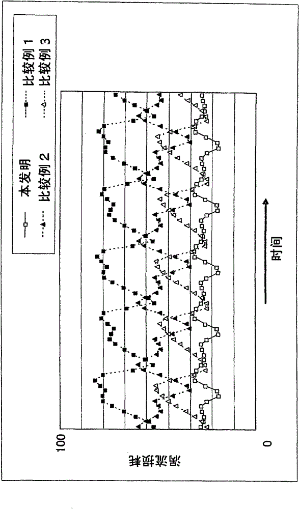
[0028] figure 1 It is a cross-sectional view schematically showing the main structure of the permanent magnet embedded type motor according to Embodiment 1 of the present invention, figure 2 It is a figure which shows the result of analyzing the eddy current loss of the permanent magnet in the permanent magnet embedded type motor which concerns on Embodiment 1 of this invention, image 3 It is a cross-sectional view schematically showing the main structure of the permanent magnet embedded motor of Comparative Example 1, Figure 4 It is a cross-sectional view schematically showing the main structure of the permanent magnet embedded type motor of Comparative Example 2, Figure 5 It is a cross-sectional view schematically showing the main structure of a permanent magnet embedded motor of Comparative Example 3, Figure 6 It is a figure explaining the reduction mechanism of the eddy current loss in the permanent magnet embedded type motor, Figure 7 It is a diagram explaining t...
Embodiment approach 2
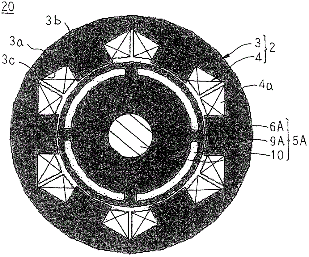
[0054] Figure 8 It is an end view schematically showing a stator core applied to a permanent magnet embedded motor according to Embodiment 2 of the present invention.
[0055] exist Figure 8 Among them, the stator core 3B is made, for example, by laminating a plurality of electromagnetic steel sheets punched into the same shape into one body, and includes an annular core rear end 3a and six teeth 11, and the six teeth 11 are respectively formed with a circumferential width The tapered shape gradually narrows toward the inner diameter side, extends radially inward from the inner peripheral surface of the core rear end 3a, and is arranged at equal angular intervals in the circumferential direction.
[0056] In addition, other structures are formed in the same manner as in Embodiment 1 described above.
[0057] According to Embodiment 2, since each tooth 11 is formed in a tapered shape in which the circumferential width becomes gradually narrower toward the inner diameter sid...
Embodiment approach 3
[0059] Figure 9 It is an end view schematically showing a stator core applied to a permanent magnet embedded motor according to Embodiment 3 of the present invention.
[0060] exist Figure 9 Among them, the core sheet 12 is made by laminating a plurality of electromagnetic steel sheets punched into the same shape, for example, and includes the core rear end portion 13, and Extended teeth 3b. The stator core 3C is configured by arranging six core pieces 12 in a ring shape in the circumferential direction and pressing them into a ring-shaped frame (not shown). Furthermore, the core rear end portions 13 are connected in the circumferential direction to constitute the core rear end 3a.
[0061] In addition, other structures are formed in the same manner as in Embodiment 1 described above.
[0062] According to the third embodiment, since the stator core 3C is divided into six core pieces 12 , the concentrated winding coils 4 a can be wound around the teeth 3 b of the core pi...
PUM
 Abstract
Description
Claims
Application Information
 - R&D Engineer
- R&D Manager
- IP Professional
- Industry Leading Data Capabilities
- Powerful AI technology
- Patent DNA Extraction
Browse by: Latest US Patents, China's latest patents, Technical Efficacy Thesaurus, Application Domain, Technology Topic.
© 2024 PatSnap. All rights reserved.Legal|Privacy policy|Modern Slavery Act Transparency Statement|Sitemap