Novel double-tooth-surface rotary ultrasonic motor stator and excitation way thereof

An ultrasonic motor, tooth surface technology, applied in the direction of generator/motor, piezoelectric effect/electrostrictive or magnetostrictive motor, electrical components, etc., can solve the failure of the motor, increase the production difficulty of the whole machine, piezoelectric ceramics Fragile and other problems, to avoid influence, improve output stability, and low modal frequency

Inactive Publication Date: 2012-10-24
NANJING UNIV OF AERONAUTICS & ASTRONAUTICS
View PDF5 Cites 8 Cited by
  • Summary
  • Abstract
  • Description
  • Claims
  • Application Information

AI Technical Summary

Problems solved by technology

However, the above inventions are all based on the process of bonding piezoelectric ceramics used in traditional rotary ultrasonic motors. When used in an extremely high temperature environment, due to the non-linearity of the adhesive layer, the piezoelectric ceramics will be fragile and the motor will fail. In addition, , in order to increase the output power, the aforementioned two comparative documents are ultrasonic motors formed by simply superimposing the two stators of the original traveling-wave ultrasonic motor; the simple superposition principle needs to optimize the working characteristics of the two stators to be very close, otherwise they will interact with each other It interferes with its working method, and due to processing errors, it is necessary to repeatedly select and compare among a large number of stators, which increases the difficulty of production of the whole machine

Method used


Image

  • Novel double-tooth-surface rotary ultrasonic motor stator and excitation way thereof
  • Novel double-tooth-surface rotary ultrasonic motor stator and excitation way thereof
  • Novel double-tooth-surface rotary ultrasonic motor stator and excitation way thereof

Examples


Embodiment Construction

[0017] The accompanying drawings disclose, without limitation, the structural schematic diagrams of the preferred embodiments involved in the present invention; the technical solution of the present invention will be described in detail below in conjunction with the accompanying drawings.

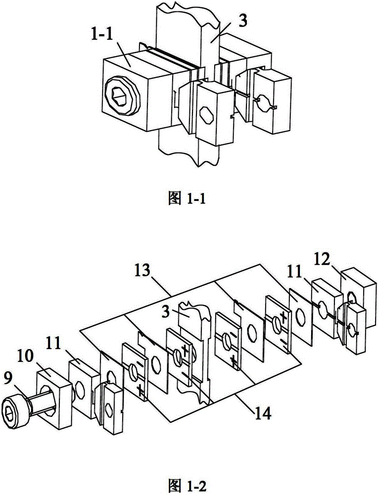
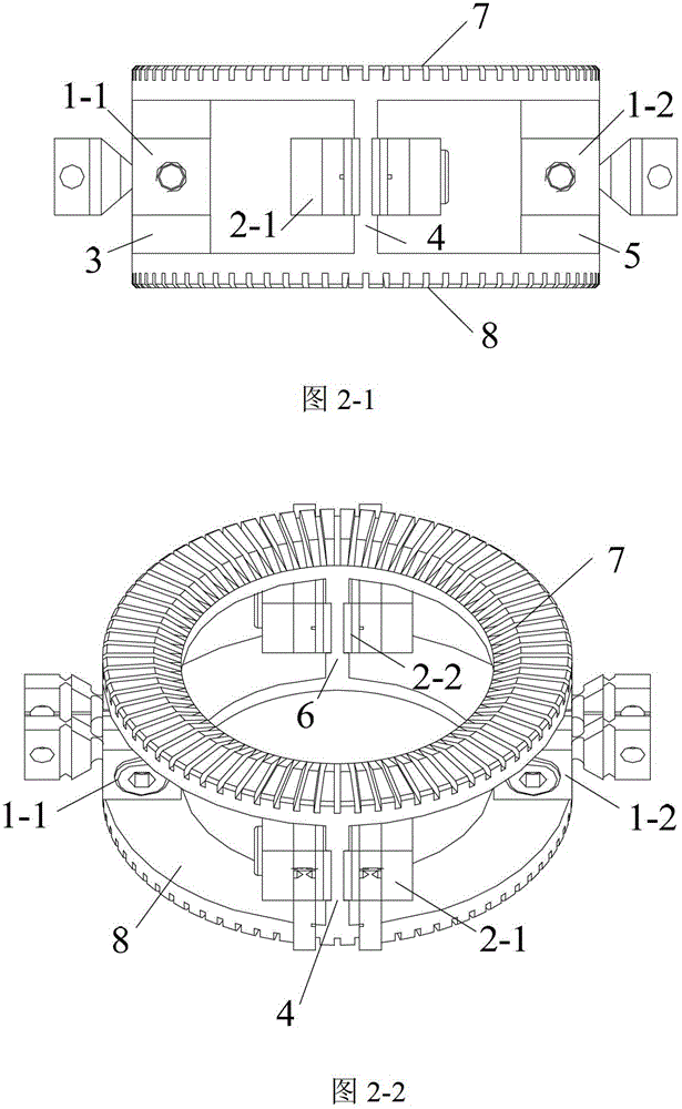
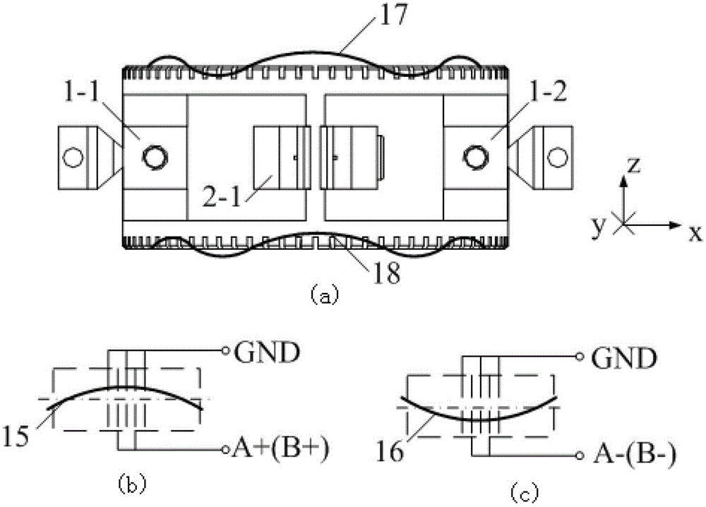
[0018] Such as diagram 2-1 , 2-2, the novel double-tooth surface rotary ultrasonic motor stator of the present invention is mainly composed of a double-tooth surface stator ring and four bending vibrators 1-1, 1-2, 2-1 and 2- 2. The double-toothed stator ring includes an upper stator ring 7, driving columns 3, 4, 5, 6, and a lower stator ring 8. Among them, the driving end surfaces of the upper stator ring 7 and the lower stator ring 8 have a tooth-shaped structure; the bending vibrator is symmetrically installed on both sides of the driving column, and is perpendicular to the driving column in the length direction; the bending vibrator is a sandwich piezoelectric composite structure, such...


PUM


Abstract

The invention discloses a novel double-tooth-surface rotary ultrasonic motor stator and an excitation way thereof. The novel double-tooth-surface rotary ultrasonic motor stator comprises a double-tooth-surface stator ring and a curved vibrator; the double-tooth-surface stator ring comprises a first stator ring and a second stator ring, which are opposite to each other, adjacent annular surfaces of the first stator ring and the second stator ring are connected with each other through four groups of drive columns, and the outer side annular surfaces of the first stator ring and the second stator ring are respectively provided with a serrate drive surface for driving a motor rotor; and each drive column is provided with one curved vibrator, the vibrators are uniformly distributed relative to a center joint line of the first stator ring and the second stator ring, and every two adjacent curved vibrators are vertical to each other in the length direction. A rotary ultrasonic motor adopting the stator structure can realize the forward-backward rotation movement and has large power output property. A motor main body has characteristics that the performance is stable, the output power is large, the structure is compact, requirement for a ceramic plate is single, the machining and assembling requirement is low, and adaptability to the running in a high-temperature environment is realized.

Description

technical field [0001] The invention relates to a stator structure, in particular to a stator structure of a rotary ultrasonic motor and an excitation method thereof. Background technique [0002] Ultrasonic motor is a new type of actuator that uses the inverse piezoelectric effect of piezoelectric ceramics to excite ultrasonic vibrations and is driven by friction. The rotary ultrasonic motor is a kind of ultrasonic motor. Compared with traditional electromagnetic motors, ultrasonic motors have the advantages of large torque-to-mass ratio, fast response, precise positioning, and no electromagnetic interference. They have broad application prospects in the fields of biomedicine, precision drives, optical devices, and aerospace. [0003] Searching the existing rotary ultrasonic motor patents found that the application number is 200910185434, which discloses a stepped shaft type rotary ultrasonic motor, which is characterized in that the two rotors are placed in the middle of ...

Claims


Application Information

Patent Timeline
Patent Type & Authority Applications(China)
IPC IPC(8): H02N2/12H02N2/14
Inventor 胡俊辉芦小龙赵淳生
Owner NANJING UNIV OF AERONAUTICS & ASTRONAUTICS
Why Eureka
Try Eureka