

Neutralisation of gaseous contaminants by means of artificial photosynthesis
A technology of artificial photosynthesis and gas, which is applied in the direction of gas treatment, use of liquid separation agent, chemical/physical/physicochemical process of energy application, etc., can solve the problem of expensive initial investment and maintenance cost
Inactive Publication Date: 2012-10-24
MASTERIDEA
View PDF8 Cites 2 Cited by
- Summary
- Abstract
- Description
- Claims
- Application Information
AI Technical Summary
Problems solved by technology
For those systems capable of capturing 99% of particulate matter, the
Method used
View moreImage
Smart ImageViewing Examples

Examples
 PUM
 Abstract
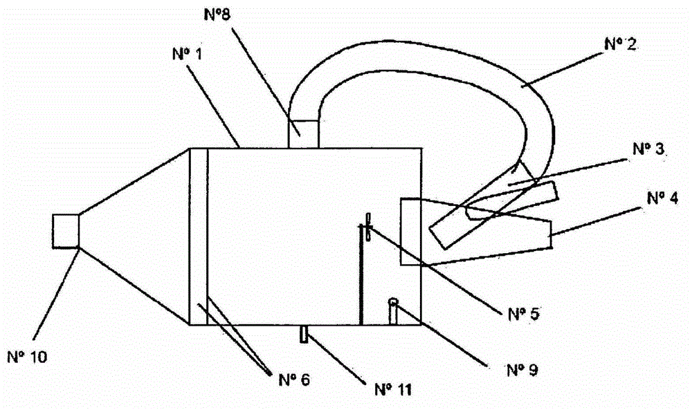
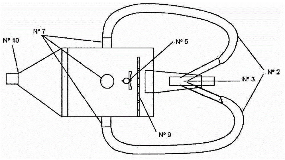
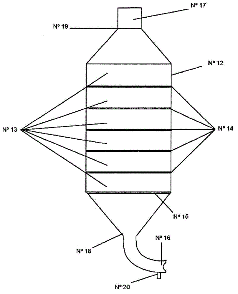
The invention relates to an artificial photosynthesis system and process used to neutralise harmful elements from any type of combustion, reducing the volume and initial pressure of the gases, by means of the kinetic energy produced by the accelerated recirculation of the gases according to the principle of molecular resonance or gas resonance, in order to then release oxygen and innocuous liquid substances by means of physical and chemical processes. Said system comprises a main chamber provided with a main gas inlet and a gas outflow tube, the main chamber comprising: a tube with nozzles arranged in the lower part of the main chamber enabling the passage of steam in the form of a steam curtain; a propeller; flexible tubes that protrude from the main chamber and connect to the main gas inlet; an electric motor for gas extraction, enabling the pressurised inflow of the gases towards the flexible tube; an evacuation duct connecting the main chamber to a secondary chamber that comprises an inlet tube for the gases from the main chamber and a gas outflow duct arranged in the upper end of the secondary chamber, the secondary chamber comprising: a plurality of connected units of plastic foam comprising a perforated sheet of aluminium at the connection points of each unit; a high-power centrifuge extractor outside the upper end of the secondary chamber; and tubes for ejecting the liquid residues, arranged in the lower part of the primary chamber and the secondary chamber.
Description
technical field [0001] The present invention relates to a system and method for neutralizing gaseous pollutants by an artificial photosynthesis autonomous system called "SAFA". Background technique [0002] It is useful to consider some technical and historical aspects of the problem of environmental pollution. The greenhouse effect is the best reference. [0003] Throughout this century, and with further global industrialization, we have witnessed a global environmental catastrophe with high levels of pollutants from the industrialization process, humans and their derivatives such as transportation and other mobile sources. The foregoing has increased the natural concentration of gases in the atmosphere, and has increased gases with higher toxicity than those that occur naturally. Among these gases, carbon monoxide (CO), carbon dioxide (CO 2 ), chlorofluorocarbons (CFCs), methane (CH 4 ), and nitrous oxide (N 2 o). [0004] The prior art relates to systems or methods ...
Claims
Login to View More Application Information
Patent Timeline
 IPC IPC(8): B01D47/06
CPCB01D2257/404B01D2257/504B01D2257/302Y02C10/04B01D53/24B01D53/50B01D53/62B01D2257/502B01D2258/0283B01D53/56Y02C20/40Y02P20/151B01D47/06B01D53/00B01D53/34B01J19/08
Inventor路易斯·文森特·冈萨雷斯·波塔莱斯让·保罗·奥利格尔·冈萨雷斯
OwnerMASTERIDEA