Optical backplane rack assembly with external optical connectors

A technology of optical connectors and optical backplanes, applied in optical components, instruments, optics, etc., can solve problems such as complex alignment strategies

Inactive Publication Date: 2012-10-24
REFLEX PHOTONICS
View PDF5 Cites 7 Cited by
  • Summary
  • Abstract
  • Description
  • Claims
  • Application Information

AI Technical Summary

Problems solved by technology

Interconnects in the prior art are also limited in that complex alignment strategies are often required
Also, since the interconnect resides deep inside the chassis near the back end, periodic cleaning of the optical interface between the connectors is quite a challenge

Method used


Image

  • Optical backplane rack assembly with external optical connectors
  • Optical backplane rack assembly with external optical connectors
  • Optical backplane rack assembly with external optical connectors

Examples


Embodiment Construction

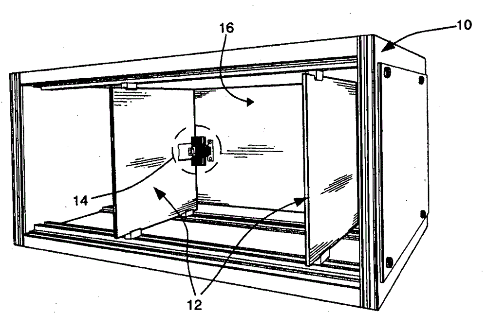
[0019] Figure 1 shows a chassis 10 for insertion of an optical line card 12 according to the prior art. As shown in this figure, the right angle optical connector 14 interconnects the middle of the optical backplane 16 with the line card 12 . Since the optical line card 12 is inserted into the optical backplane 16 towards the optical backplane, perpendicular to the plane of the optical waveguide, an optical "square corner" is required in the connector 14 . Typical prior art methods for coupling light between the optical line card 12 and the optical backplane 16 place light sources such as microlasers and photodetectors on the back of the optical line card 12 (i.e., the line card is closest to the backplane side of the backplane 16) and use complex mechanisms to automatically align the light sources into the holes done on the inside of the optical backplane 16. Since these optical right-angle corner connectors 14 are generally sensitive to misalignment and prone to coupling lo...


PUM


Abstract

There is described a line card rack assembly for line cards, and an optical backplane and optical fiber guide for installation to a frame adapted to receive line cards of which at least one has an optical connector at a front portion thereof. The rack assembly comprises a frame having a front opening, for receiving the line cards and providing access to a front end of the line cards, and a back opening opposite the front opening; an optical backplane at least partially covering the back opening, the optical backplane comprising connections for connecting the line cards upon insertion in the frame; and optical fiber cable having two ends, a first one of the two ends being for coupling to the optical backplane, and a second one of the two ends for coupling to the optical connector of the at least one of the line cards.

Description

[0001] Cross References to Related Applications [0002] This application claims priority to prior established US Application Serial No. 12 / 618,309, filed November 13, 2009, entitled "OPTICAL BACKPLANE RACK ASSEMBLY WITH EXTERNAL OPTICAL CONNECTORS." technical field [0003] The present disclosure relates to electronic devices and optical data communications, and more particularly, to blade servers and line card chassis. Background technique [0004] Increasing efforts have been made to increase the switching and processing capabilities of systems used in telecommunications and computing frameworks. Optical solutions have been shown to be an efficient way to go in the future. [0005] Challenges arise in making electrically based systems optically compatible. In electrically switched systems and servers, for example, the backplane of a chassis containing electronic circuit cards (also referred to herein as line cards, blades, nodes, or switch cards) allows electrical signa...

Claims


Application Information

Patent Timeline
Patent Type & Authority Applications(China)
IPC IPC(8): H04Q1/04H04B10/02
CPCH04Q1/09H04Q1/025G02B6/4452H04Q1/155
Inventor 大卫·R·罗尔斯顿
Owner REFLEX PHOTONICS
Why Eureka
Try Eureka