Manufacturing method of blade type product die forging clot

A manufacturing method and a blank blank technology are applied to the manufacturing method of die-forged blank blanks for blade products and the field of special molds, which can solve the problems of uneven metal distribution, enlarged dressings, complicated processes, etc., so as to save energy and raw materials, The effect of raw material specification reduction and process safety

Active Publication Date: 2012-10-31
DONGFANG TURBINE CO LTD
View PDF2 Cites 8 Cited by
  • Summary
  • Abstract
  • Description
  • Claims
  • Application Information

AI Technical Summary

Problems solved by technology

[0005] 1) It cannot fully meet the requirements of the blanking process, and the size is not easy to control, resulting in uneven metal distribution in various parts of the blank, and some parts often need to increase the dressing;
[0006] 2) The transition R part is difficult to control, and there are many folds and cracks in these parts. After the billet is opened, it takes a lot of manpower and material resources to polish it, and it is not easy to polish it clean, which seriously affects the quality of subsequent die forging;
[0007] 3) The surface of the blank is not smooth, and it is easy to have defects such as folding in the subsequent die forging;
[0008] 4) The required membranes and tooling are heavy, it is difficult to operate manually, and there are many safety hazards;
[0009] 5) The whole process is complex, with many forging fires and large material consumption
[0013] 3) The forming of the large ends at both ends still needs to be formed by upsetting on the free forging, the required membrane and tooling are heavy, it is difficult to operate manually, and there are many safety hazards

Method used


Image

  • Manufacturing method of blade type product die forging clot
  • Manufacturing method of blade type product die forging clot
  • Manufacturing method of blade type product die forging clot

Examples


Embodiment Construction

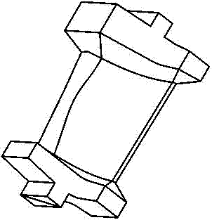
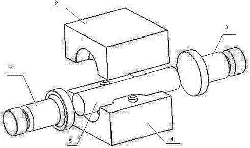
[0052] Such as Figure 3-6 As shown, in order to improve the shortcomings of the blank blank 6 of the blade in the past, the present invention makes corresponding improvements to the manufacturing scheme of the blank blank 6. The present invention adopts the upsetting technology to manufacture the blank blank 6 of blade products. Specifically, the heated cylindrical bar 5 is arranged in the billet mold, and the diameter of the blank 6 is smaller than or equal to the diameter of the bar 5 .

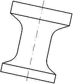
[0053] Such as figure 2 As shown, the die forging blank 6 of the blade product is dumbbell-shaped, and is formed by connecting the big discs at the left and right ends and the middle rod, and the big disc and the middle rod are connected smoothly through the transition arc surface.

[0054] Such as Figure 6 As shown, according to the principle of upsetting forging, a special billet mold is designed. The billet mold is a horizontal two-opening mold structure, which is divided into an up...


PUM


Abstract

The invention provides a manufacturing method of a blade type product die forging clot. The blade type product die forging clot is dumbbell-shaped and is formed by connecting large-end discs at left and right ends and a middle-section rod member, wherein the large-end discs and the middle-section rod member are in smooth connection with one another through transition cambered surfaces; the clot is prepared by using an upset forging machining process; a cylindrical rod material is arranged in a mould; the mould has a horizontal double-opening mould structure; the size of a cavity after closing of an upper die and a lower die is consistent with the size of the clot; the left end and the right end of the cavity are provided with a left upset head and a right upset head respectively; and the left upset head and the right upset head move oppositely to extrude the two ends of the rod, so that the rod is made into the clot in the mould through upset forging. The manufacturing method has the comprehensive advantages of die forging and extrusion; the limitation of free forging hammer and radial forging is broken through; the backwardness of large coating, large margin and tolerance and fatness of normal clots is changed; fine production of the clot can be realized; the manufacturing process is finished at one time; the operation time is short; the forming accuracy of the clot is high.

Description

technical field [0001] The invention relates to the field of manufacturing and processing blades of turbine equipment, in particular to a method for manufacturing blade-like product die-forging blanks and a special mold thereof. Background technique [0002] Blades are the core components of turbine equipment such as steam turbines and compressors, and play a key role in energy conversion. With the development of blade technology, the shape and structure of blades are becoming more and more complex, the surface distortion is large, and the blade blanks with long steam passages are generally formed by die forging. figure 1 It is a typical steam turbine blade die forging blank. Because of its unique structure with two large ends and a small middle, in order to ensure the filling of the blank during the die forging process, the prefabricated blank also needs to be forged into a corresponding "dumbbell" shape, such as figure 2 shown. [0003] The prior art generally adopts th...

Claims


Application Information

Patent Timeline
Patent Type & Authority Applications(China)
IPC IPC(8): B21J5/02B21K3/04
Inventor 谢彬刘明松王虹钟杰刘仁君龙正建邓凌宇李波何应强蒋峥嵘徐绍明李森
Owner DONGFANG TURBINE CO LTD
Why Eureka
Try Eureka