AI technical title is built by Patsnap AI team. It summarizes the technical point description of the patent document.
A life-saving machine and tunnel technology, applied in the field of rescue equipment and tunnel collapse life-saving machines, can solve problems such as reports of tunnel collapse life-saving machines that have not yet been seen
Active Publication Date: 2012-10-31
CHINA RAILWAY ENGINEERING EQUIPMENT GROUP CO LTD
View PDF6 Cites 14 Cited by
Summary
Abstract
Description
Claims
Application Information
AI Technical Summary
This helps you quickly interpret patents by identifying the three key elements:
Problems solved by technology
Method used
Benefits of technology
Problems solved by technology
[0004] The present invention aims to release a special life-saving machine, but there are no reports about this type of tunnel collapse life-saving machine at home and abroad.
Method used
Image
Click on the blue label to locate the original text in one second.
Reading with bidirectional positioning of images and text.
Examples
Embodiment 1
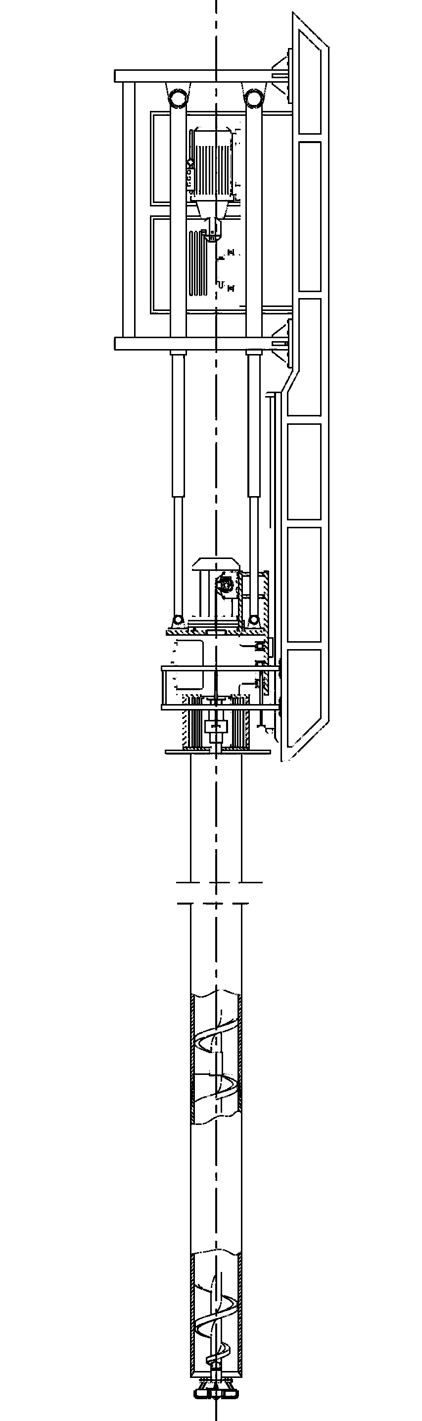
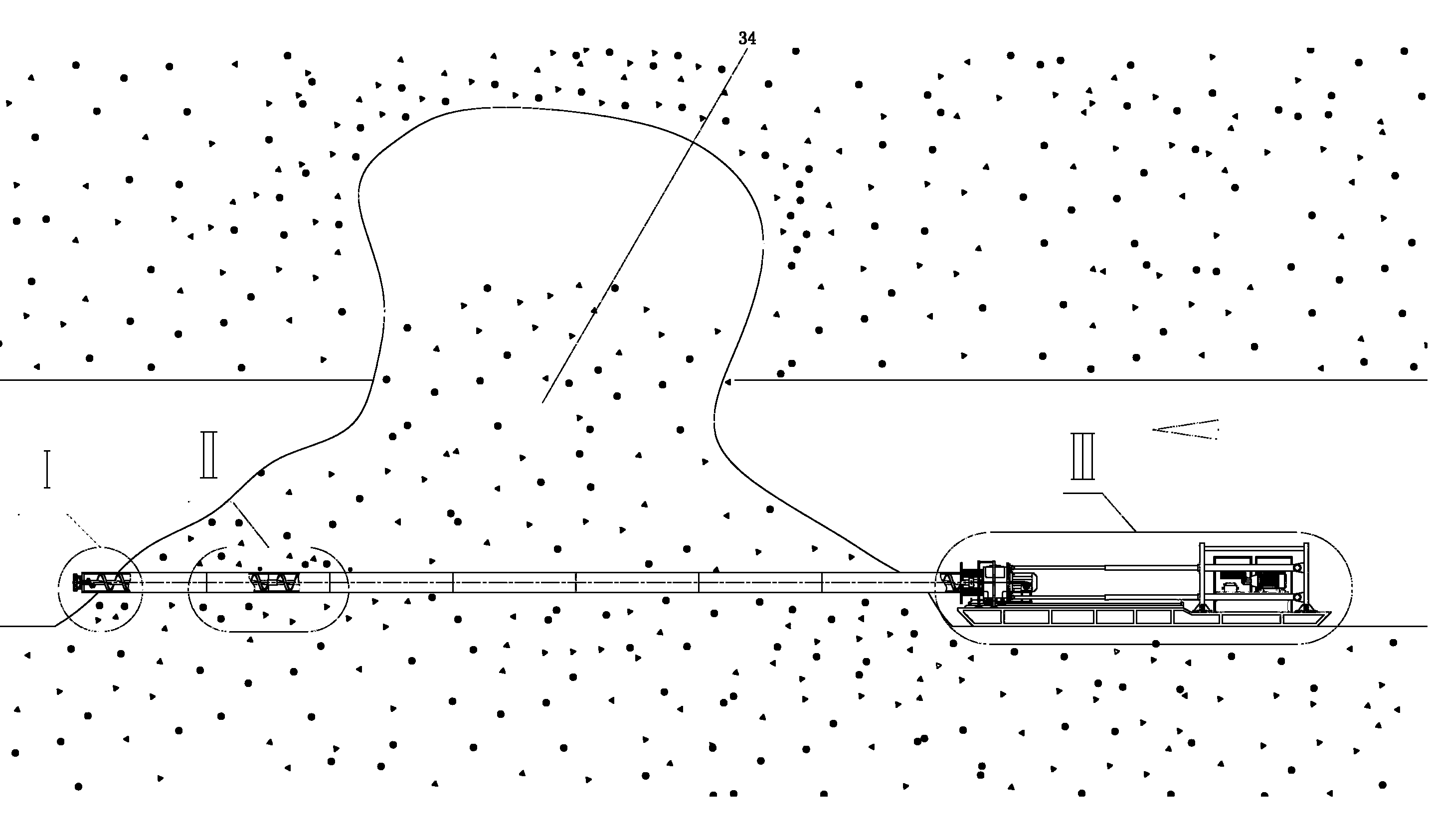
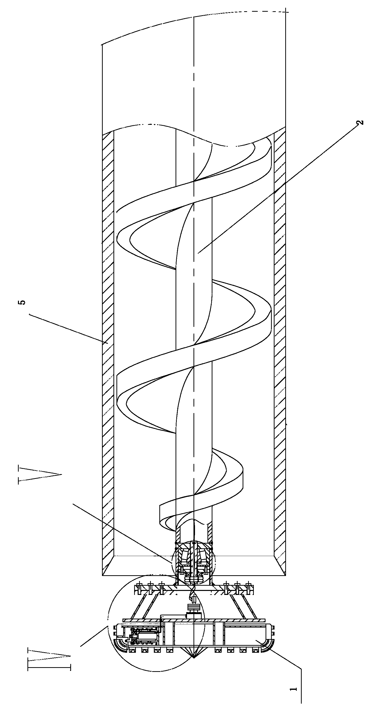
[0032] Such as figure 1 , figure 2 , image 3 , Figure 4 , Figure 5 , Figure 6 , Figure 7 , Figure 8 , Figure 9 , Figure 10 and Figure 11 as shown, figure 2 The middle arrow shows the tunneling direction. The serial numbers in the figure are as follows: 1. Cutting head with variable diameter function, 2. Screw conveying shaft, 3. Drive motor, 4. Hollow shaft reducer, 5. Life preserver, 6. Propelling cylinder, 7. Auxiliary cylinder, 8. Sliding base, 9, sliding shoe, 10, guide rail, 11, electric winch, 12, angular contact bearing, 13, thrust bearing, 14, oil tank, 15, pumping station motor, 16, hydraulic pump, 17, valve group, 18, Power distribution cabinet, 19, control cabinet, 20, chassis, 21, bed, 22, bed skids, 23, head cover, 24, coupling, 25, squirrel cage thrust frame, 26, end of life preserver Transition joint, 27, side scraper, 28, steel wire rope, 29, hinge, 30, mandrel, 31, bearing seat, 32, screw conveyor shaft extension joint, 33, safety belt, ...
Embodiment 2
[0058] Such as figure 1 , figure 2 , image 3 , Figure 4 , Figure 5 , Figure 6 , Figure 7 , Figure 8 , Figure 9 , Figure 10 , Figure 11 , Figure 12 , Figure 13 and Figure 14 shown. The lifesaving machine structure and lifesaving process of this embodiment are basically the same as those of Embodiment 1, but also have the following differences.
[0059] The driving motor in the rotary drive device of the screw conveying shaft is changed to a hydraulic motor, and the electric winch is changed to a hydraulic winch.
[0060] For the convenience of transportation, the chassis 20 is changed from integral type to split type. It is composed of 2 boxes, the split plane is located in the middle, and each of the two boxes is provided with a connection plate, which is connected with high-strength bolts. The split type chassis is convenient. Transportation under construction.
[0061] After forming a transparent space in the life-saving cylinder 5, use a commerci...
PUM
Abstract
The invention relates to a tunnel collapse life savingmachine. The tunnel collapse life savingmachine comprises a diameter-varying cutting head, a screw conveying shaft, a screw conveying shaft rotation drive device, a life-saving barrel, a propulsion system, a hydraulic pumpstation, a base plate, a power distribution cabinet and a control cabinet, wherein the screw conveying shaft is sleeved in the life-saving barrel. According to the life savingmachine, the diameter-varying cutting head is used for cutting collapsed soil bodies in a manner of breaking rock; the excavation diameter can be timely adjusted in the propulsion process; cutmuck is discharged form the rear end of the life-saving barrel through the screw conveying shaft; the life-saving barrel is propelled along with the propulsion of the screw conveying shaft; when the screw conveying shaft is drawn out, the life-saving barrel forms a safe passage, so that personnel trapped by collapse in the tunneling process can be quickly and safely rescued in a human-friendly manner; meanwhile, the screw conveying shaft and the life-saving barrel in the life saving machine consist of a plurality of sections, are lengthened in a manner of changing steps and facilitate long distance excavation; and a steel wire rope is used for tensioning the front end of the screw conveying shaft, so that the downwarping of the screw conveying shaft is reduced, and the normal work is ensured.
Description
technical field [0001] The invention belongs to the field of machinery, in particular to rescue equipment, in particular to a tunnel collapse lifesaving machine. Background technique [0002] During the excavation of tunnels, landslides sometimes occur suddenly due to geological reasons. If the landslide occurs behind the workers on the excavation surface of the tunnel, the passage between the workers and the back of the tunnel may be cut off, and they will be in a state of lack of oxygen, drinking water and food. If there are injured people, they will also be in a dangerous situation because they cannot receive timely medical treatment. The traditional method of carrying out emergency rescue to the trapped people is to adopt engineering machinery such as excavators, loaders, multi-functional drilling rigs, rock drills to carry out rescue or drill holes and shoot. Due to the large earthwork workload, large soil disturbance and the possibility of partial blasting, there are...
Claims
Application Information
Patent Timeline
Application Date:The date an application was filed.
Publication Date:The date a patent or application was officially published.
First Publication Date:The earliest publication date of a patent with the same application number.
Issue Date:Publication date of the patent grant document.
PCT Entry Date:The Entry date of PCT National Phase.
Estimated Expiry Date:The statutory expiry date of a patent right according to the Patent Law, and it is the longest term of protection that the patent right can achieve without the termination of the patent right due to other reasons(Term extension factor has been taken into account ).
Invalid Date:Actual expiry date is based on effective date or publication date of legal transaction data of invalid patent.
Patent Type & AuthorityApplications(China)
IPC IPC(8): E21F11/00E21D9/10E21D9/12
CPCE21F11/00E21D9/00E21B17/00E21B7/201
Inventor李建斌何於琏
OwnerCHINA RAILWAY ENGINEERING EQUIPMENT GROUP CO LTD

