
Phase-shifting mask with auxiliary phase areas

A technology of phase shift mask and phase, applied in the field of phase shift mask

Inactive Publication Date: 2012-10-31
ULTRATECH INT INC
View PDF12 Cites 4 Cited by
  • Summary
  • Abstract
  • Description
  • Claims
  • Application Information

AI Technical Summary

Problems solved by technology

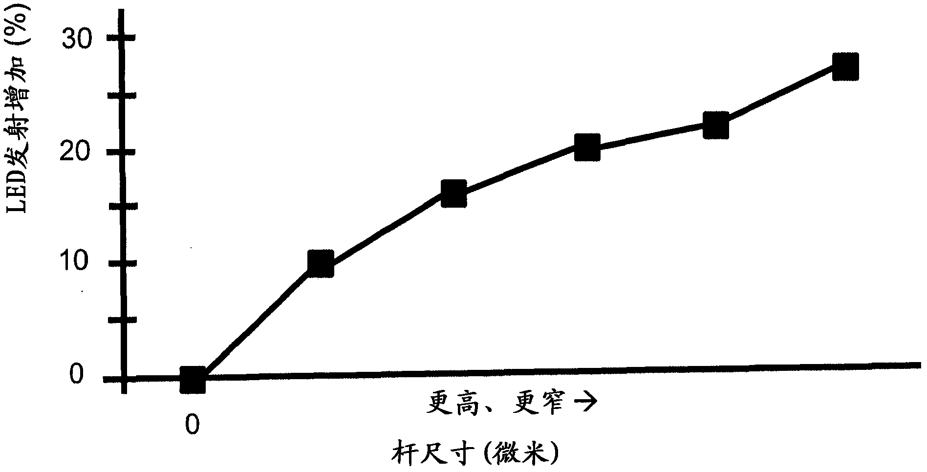
However, a general limitation on the light emission efficiency of LEDs is due to the total internal reflection of light generated within the LED

Method used


Image

  • Phase-shifting mask with auxiliary phase areas
  • Phase-shifting mask with auxiliary phase areas
  • Phase-shifting mask with auxiliary phase areas

Examples


Embodiment Construction

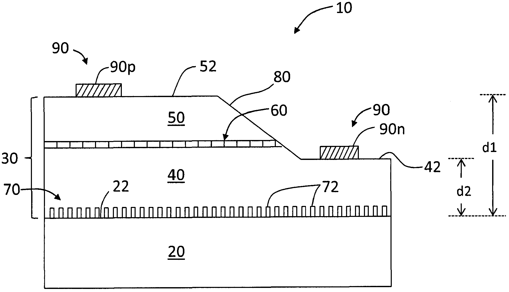
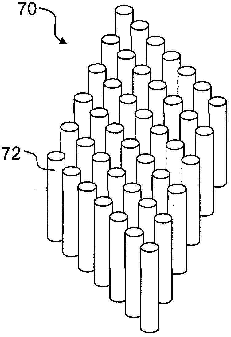
[0050] Reference will now be made in detail to the various embodiments of the present disclosure, examples of which are illustrated in the accompanying drawings. Wherever possible, the same or similar reference numbers and symbols are used throughout the drawings to refer to the same or similar parts. The drawings are not necessarily to scale, and those skilled in the art will recognize that the drawings have been simplified to illustrate key aspects of the disclosure. For example, with respect to the phase shift masks disclosed herein, such masks can contain many thousands of phase regions, and in some figures a limited number of phase regions are shown as illustrations.

[0051] Aspects of the phase shift mask with auxiliary phase regions of the present disclosure are discussed exemplarily in connection with the fabrication of LEDs. Accordingly, information pertaining to LED structure and fabrication by photolithography is set forth below.

[0052] Exemplary LED Structure ...


PUM


Abstract

The invention provides a phase-shifting mask with auxiliary phase areas. The phase-shifting mask comprises a tessellate array and a surrounding sub-resolution ratio auxiliary phase graph, wherein the tessellate array comprises an alternating phase-shifting area R having 180 degree of relative phase difference; the sub-resolution ratio auxiliary phase area R stays in the adjacent and corresponding phase-shifting area R and has 180 degree of relative phase difference relative to the phase-shifting area R; and the sub-resolution ratio auxiliary phase area R is configured in a way that reduces the unnecessary edge effect while using photo-etching to form photoresist characteristics. The invention also discloses a method for using the phase-shifting mask to form an LED.

Description

[0001] Cross Reference Related Applications [0002] This application is a continuation-in-part of US Patent Application Serial No. 12 / 928,862, filed December 21, 2010, entitled "Photolithographic LED fabrication using phase-shift mask," which is incorporated herein by reference. technical field [0003] The present disclosure relates generally to phase shift masks for use in lithography, and more particularly to phase shift masks with auxiliary phase regions. Background technique [0004] Phase shift masks are used in various photolithographic applications to form semiconductor integrated circuits and light emitting diodes (LEDs). The phase shift mask is different from the commonly used chrome-on-glass (chrome-on-glass) mask in that the transparent areas in the phase shift mask have a relative phase difference, while in the chrome-on-glass mask, the transparent areas all have the same relative phase difference. phase. An advantage of the selective phase difference of the ...

Claims


Application Information

Patent Timeline
IPC IPC(8): G03F1/26G03F7/20H01L33/00H01L33/22
Inventor R・L・辛赫W・W・弗莱克
Owner ULTRATECH INT INC
Learn More