Motor rotor and motor with motor rotor

An electric motor and rotor technology, applied in the field of electric motors, can solve the problems of inability to meet the urgent requirements of electric motor efficiency, limitations, high price, etc., and achieve the effects of improving electric motor efficiency, reducing the amount of rare earth, and increasing reluctance torque

Active Publication Date: 2012-10-31
GREE ELECTRIC APPLIANCES INC +1
View PDF4 Cites 3 Cited by
  • Summary
  • Abstract
  • Description
  • Claims
  • Application Information

AI Technical Summary

Problems solved by technology

However, since rare earths are non-renewable resources and are expensive, the wider application of this type of motor is limited
In addition, improving the performance of the motor only by improving the performance of the permanent magnet cannot meet the urgent requirements of further improving the efficiency of the motor.

Method used


Image

  • Motor rotor and motor with motor rotor
  • Motor rotor and motor with motor rotor
  • Motor rotor and motor with motor rotor

Examples


no. 1 example

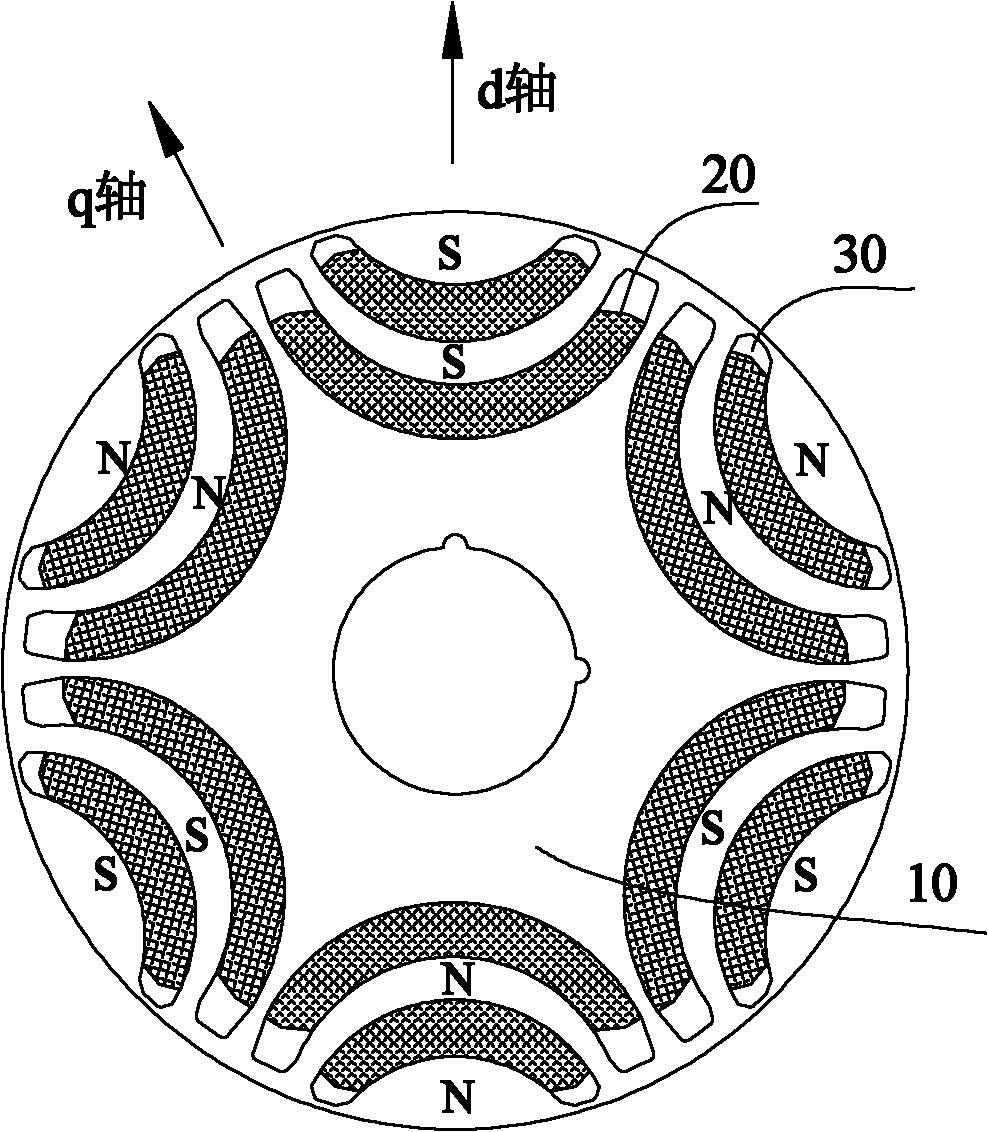
[0033] Such as figure 1 As shown in the first embodiment of the engine rotor according to the present invention, the motor rotor includes an iron core 10 and a permanent magnet 20 disposed inside the iron core 10, and the iron core 10 is provided with multiple sets of mounting grooves 30 along the circumferential direction of the iron core 10, Each group of mounting grooves 30 includes two or more than two mounting grooves 30 intermittently arranged in the radial direction of the iron core 10; there are multiple groups of permanent magnets 20, and each permanent magnet 20 in each group of permanent magnets 20 is embedded in each group correspondingly. In each of the installation grooves 30 of the installation grooves 30 .

[0034] figure 1 The iron core 10 of the engine rotor in the engine is made of laminated silicon steel plates and has a certain stack height. With the axis of the iron core 10 as the center of the circle, six sets of mounting grooves 30 are evenly distribut...


PUM


Abstract

The invention provides a motor rotor and a motor with the motor rotor. The motor rotor provided by the invention comprises an iron core and permanent magnets which are arranged inside the iron core, wherein multiple groups of mounting grooves are arranged on the iron core along the circumferential direction of the iron core; each group of the mounting grooves comprises two or more mounting grooves which are arranged discontinuously in the radial direction of the iron core; multiple groups of the permanent magnets are arranged; and each permanent magnet in each group of the permanent magnets is correspondingly embedded in each mounting groove in each group of the mounting grooves. The motor provided by the invention comprises the motor rotor. According to the motor rotor and the motor withthe motor rotor, the reluctance torque of the motor rotor is improved, so that the output torque of the motor is improved and the efficiency of the motor is improved. In addition, the efficiency of the motor is improved without additionally arranging rare-earth permanent magnets, so that the rare-earth usage is reduced; on the one hand, the energy source is saved and the environmental burden is lightened; and on the other hand, the cost is reduced and the product competitiveness is promoted.

Description

technical field [0001] The invention relates to the field of electric motors, more specifically, to a motor rotor and a motor having the same. Background technique [0002] A permanent magnet synchronous motor (IPM) is a motor that places a layer of permanent magnets inside the rotor and mainly uses permanent magnet torque and reluctance torque as auxiliary motors. [0003] The synthetic formula of reluctance torque and permanent magnet torque is as follows: T=mp(L q -L d )i d i q +mpψ PM i q . [0004] Among them, T is the output torque of the motor, increasing the value of T can improve the performance of the motor; the first term in the equation after T is the reluctance torque, and the second term is the permanent magnet torque; Ψ PM is the maximum value of the stator-rotor coupling magnetic flux generated by the permanent magnet of the motor, m is the phase number of the stator conductor, L d , L q They are the d-axis and q-axis inductance respectively, where t...

Claims


Application Information

Patent Timeline
Patent Type & Authority Applications(China)
IPC IPC(8): H02K1/27H02K21/12
CPCH02K1/2766H02K2213/03H02K1/246
Inventor 黄辉胡余生陈东锁陈华杰肖勇曾学英张文明
Owner GREE ELECTRIC APPLIANCES INC
Why Eureka
Try Eureka