Permanent-magnetic rotor with non-magnetic-permeable distance sleeve and method for manufacturing permanent-magnet rotor

A technology of permanent magnet rotor and manufacturing method, which is applied in the direction of magnetic circuit rotating parts, manufacturing stator/rotor body, magnetic circuit shape/style/structure, etc. It is too suitable for problems such as magnetic flux leakage at the axial end of the rotor, so as to reduce the magnetic leakage interference problem, improve the anti-electromagnetic interference and electromagnetic compatibility capabilities, and achieve the effect of low magnetic flux leakage at the axial end.

Inactive Publication Date: 2012-10-31
LINQUAN AEROSPACE MOTOR CO LTD
View PDF5 Cites 21 Cited by
  • Summary
  • Abstract
  • Description
  • Claims
  • Application Information

AI Technical Summary

Problems solved by technology

However, the existing permanent magnet interpolated rotors for permanent magnet motors generally have the problem of magnetic flux leakage at the axial ends, and the pressure plates on both sides of the rotor axial direction must be made of non-magnetic materials, otherwise the rotor axial The flux leakage at the end is more serious
And this kind of rotor that uses non-magnetic materials to make both side end pressure plates not only has the disadvantages of large volume and low magnetic efficiency, but also has the problems of low strength and short service life; in addition, the permanent magnets in the prior art The rotor shaft of the magneto rotor is generally made of magnetically permeable materials, and the rotor core is directly installed on the rotor shaft, so the phenomenon of magnetic leakage through the rotor shaft is very serious. For some applications requiring small magnetic interference, the existing These permanent magnet motors are not suitable
Therefore, the use effect of the existing permanent magnet motor rotor is not ideal enough.

Method used


Image

  • Permanent-magnetic rotor with non-magnetic-permeable distance sleeve and method for manufacturing permanent-magnet rotor
  • Permanent-magnetic rotor with non-magnetic-permeable distance sleeve and method for manufacturing permanent-magnet rotor
  • Permanent-magnetic rotor with non-magnetic-permeable distance sleeve and method for manufacturing permanent-magnet rotor

Examples


Embodiment 1

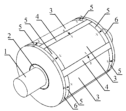
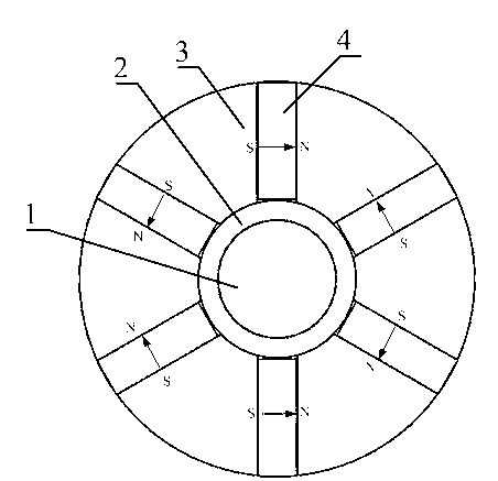
[0021] Embodiment 1 of the present invention: when making the rotor of the permanent magnet motor, adopt a kind of manufacturing method of the permanent magnet rotor that is provided with non-magnetic spacer sleeve of the present invention to make, when making, put one on the rotor shaft earlier A non-magnetic isolation sleeve made of non-magnetic material, the non-magnetic material can be made of existing aluminum, aluminum alloy, copper, copper alloy, or stainless steel; then the rotor core is made into a fan shape, and the fan-shaped rotor core Evenly distributed and fixed on the non-magnetic isolation sleeve, and at the same time, each fan-shaped rotor core installed and fixed on the non-magnetic isolation sleeve except its arc-shaped upper end surface and the contact surface with the non-magnetic isolation sleeve, the other four sides The permanent magnet blocks made of permanent magnet materials are used to fit and surround them, and the magnetic poles of each permanent m...

Embodiment 2

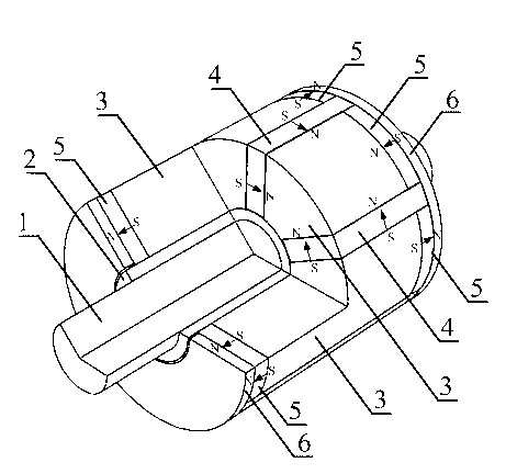
[0023] Embodiment 2: When making the permanent magnet rotor provided with the non-magnetic spacer sleeve of the present invention, it can be made according to the method of Embodiment 1. When making, the two adjacent second permanent magnet blocks 5 can also be The two sides bear against each other, and the two ends of the first permanent magnet 4 are respectively pushed against the inner end faces of the second permanent magnet 5 at both ends (such as Figure 6 shown); the rest of the production methods are the same as in Example 1.

Embodiment 3

[0024] Embodiment 3: when making the permanent magnet rotor provided with the non-magnetic spacer sleeve of the present invention, it can be made according to the method of embodiment 1. When making, the two adjacent second permanent magnets 5 can also be There is a gap between the two sides, so that the two ends of the first permanent magnet 4 are respectively facing the gap positions of the two second permanent magnets 5 adjacent to the two ends (such as Figure 7 shown); the rest of the production methods are the same as in Example 1.


PUM


Abstract

The invention discloses a permanent-magnetic rotor with a non-magnetic-permeable distance sleeve and a method for manufacturing the permanent-magnetic rotor. The method includes sleeving the non-magnetic-permeable distance sleeve made of a non-magnetic-permeable material on a rotor shaft at first when iron cores of the rotor are mounted on the rotor shaft; then manufacturing the iron cores of the rotor into fan-shaped iron cores; uniformly distributing and fixedly mounting the fan-shaped iron cores of the rotor on the non-magnetic-permeable distance sleeve; encircling four surfaces, except for the arc-shaped upper end surface and a contacting surface with the non-magnetic-permeable distance sleeve, of each fan-shaped iron core, which is fixedly mounted on the non-magnetic-permeable distance sleeve, of the rotor by permanent magnets made of permanent magnetic materials in an attached manner; and arranging attached surfaces of the permanent magnets and the fan-shaped iron cores of the rotor properly so that magnetic polarities of the attached surfaces of the permanent magnets and the fan-shaped iron cores are identical correspondingly. The permanent-magnetic rotor has the advantages that the permanent-magnetic rotor is compact in structure, high in interference resistance, stable in work performance and long in service life, flux leakage at axial ends and flux leakage interference of the rotor are low, magnetic efficiency and utilization rate of each permanent magnet are high, and the like.

Description

technical field [0001] The invention relates to a permanent magnet rotor provided with a non-magnetic isolation sleeve and a manufacturing method thereof, belonging to the technical field of permanent magnet motor manufacturing. Background technique [0002] Permanent magnet motors have the advantages of high efficiency and high power density, and have recently received more and more attention. Among them, the permanent magnet interpolation motor has the advantages of simple processing, and the permanent magnet of the rotor can realize the magnetization effect, which is a kind of permanent magnet motor widely used. However, the existing permanent magnet interpolated rotors for permanent magnet motors generally have the problem of magnetic flux leakage at the axial ends, and the pressure plates on both sides of the rotor axial direction must be made of non-magnetic materials, otherwise the rotor axial The flux leakage at the end is more serious. And this kind of rotor that ...

Claims


Application Information

Patent Timeline
Patent Type & Authority Applications(China)
IPC IPC(8): H02K15/03H02K1/27
Inventor 沈建新王灿飞
Owner LINQUAN AEROSPACE MOTOR CO LTD
Why Eureka
Try Eureka