Impeller, electric air blower using same, and electric cleaner using electric air blower

A blower and impeller technology, which is applied in the fields of impellers, electric blowers using the impeller and vacuum cleaners using the electric blower, can solve the problems of unrealistic, high cost, difficulty in mass production by casting method, etc. high performance effects

Inactive Publication Date: 2012-10-31
PANASONIC INTELLECTUAL PROPERTY MANAGEMENT CO LTD
View PDF6 Cites 6 Cited by
  • Summary
  • Abstract
  • Description
  • Claims
  • Application Information

AI Technical Summary

Problems solved by technology

However, since the blade portion 125a of the inducer 125 has a complex three-dimensional shape, it is difficult to manufacture the blade portion 125a using a mold when the number of blade portions 125a is increased.
In addition, it is conceivable to produce the blade portion 125a using a casting method such as a casting, but the casting method is difficult to mass-produce and the cost is very high, so it is not practical.

Method used


Image

  • Impeller, electric air blower using same, and electric cleaner using electric air blower
  • Impeller, electric air blower using same, and electric cleaner using electric air blower
  • Impeller, electric air blower using same, and electric cleaner using electric air blower

Examples


Embodiment approach 1

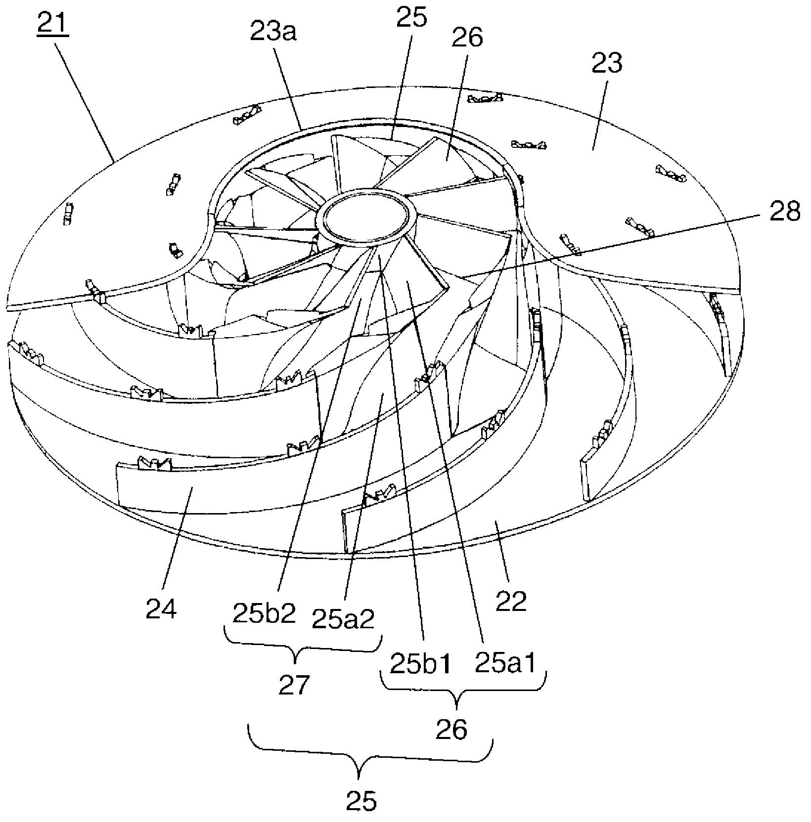
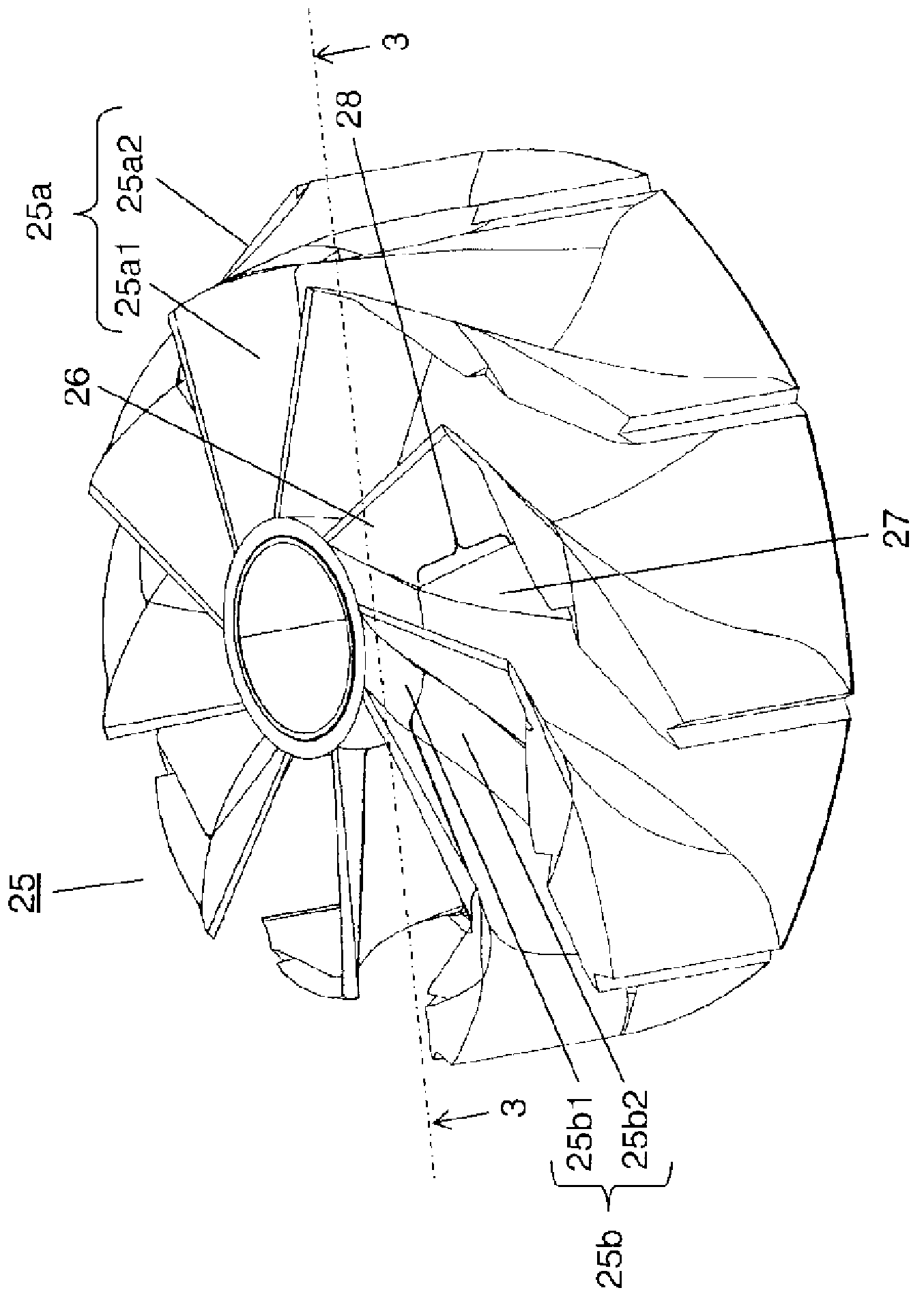
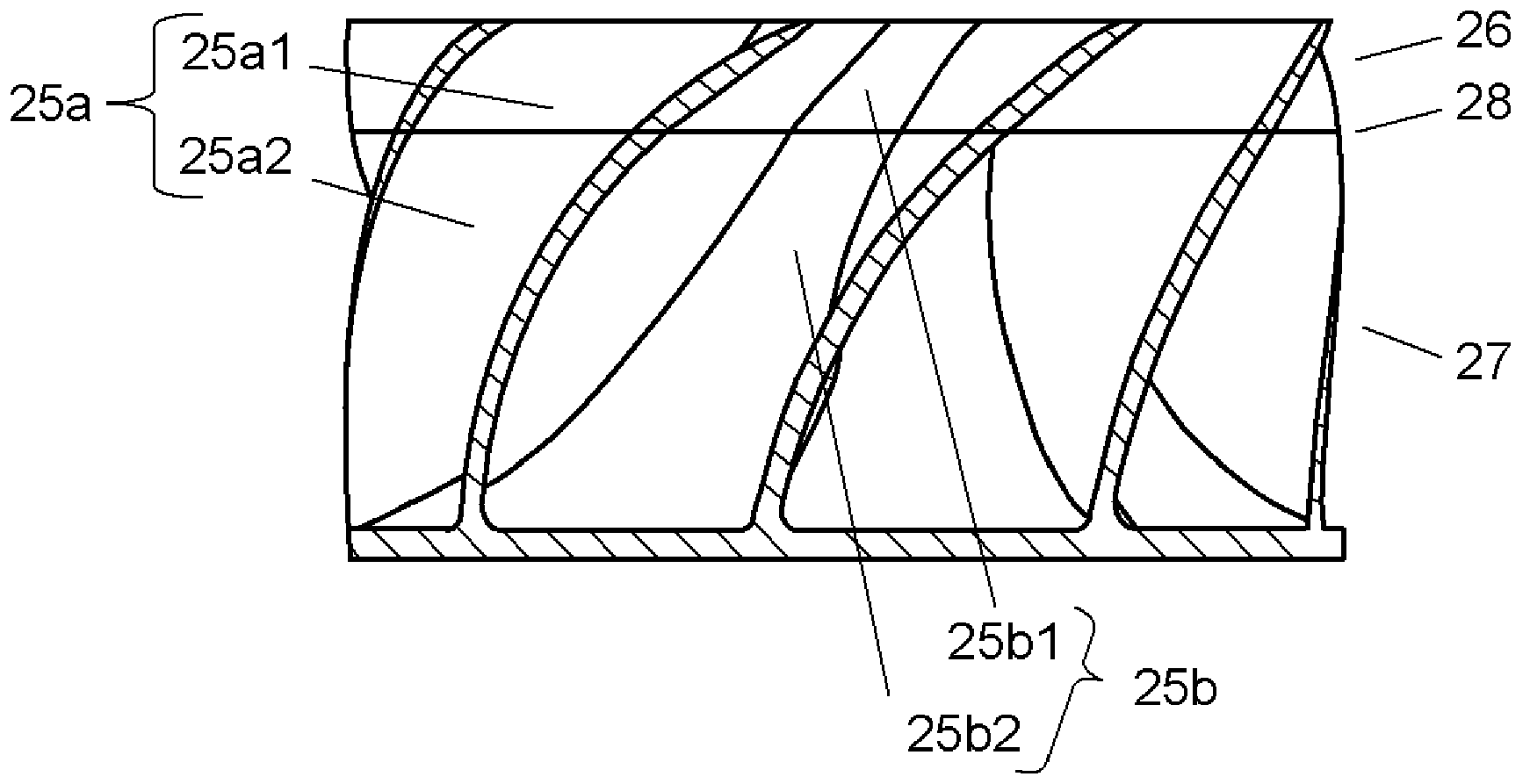
[0040] figure 1 It is a cutaway perspective view explaining the structure of the impeller in Embodiment 1 of this invention. figure 2 It is a perspective view of the inducer of the impeller in Embodiment 1 of this invention. image 3 of the impeller according to Embodiment 1 of the present invention figure 2 View of the 3-3 wire inducer. Figure 4 It is a plan view of the first inducer of the impeller according to Embodiment 1 of the present invention. Figure 5 It is a perspective view showing the second inducer of the impeller according to Embodiment 1 of the present invention. In addition, since the structure of the electric blower with the impeller installed on the motor is basically the same as that of the conventional electric blower, please refer to Figure 17 Be explained.

[0041] Hereinafter, the impeller mounted on the motor of the electric blower will be described in detail.

[0042] Such as figure 1 shown, is motor 7 (refer to Figure 17 ) The impeller...

Embodiment approach 2

[0066] Figure 9 is the inducer constituting the impeller according to Embodiment 2 of the present invention figure 2 3-3 line view.

[0067] The impeller of this embodiment differs from Embodiment 1 in that at least one side of the joint portion 28 between the first blade portion 25a1 of the first inducer 26 and the second blade portion 25a2 of the second inducer 27 is Grooves 29 are provided on the joint face. In addition, other structures are the same as those of Embodiment 1.

[0068] Such as Figure 9 As shown, the inducer 25 of the impeller 21 in this embodiment is provided with a groove 29 on the joint surface along the joint portion 28 between the first blade portion 25 a 1 of the first inducer 26 and the second inducer 27 . Then, an adhesive is applied in the groove 29 to bond the first blade portion 25 a 1 of the first inducer 26 and the second inducer 27 . At this time, since the adhesive flows along the grooves 29, the adhesive can be applied efficiently and ...

Embodiment approach 3

[0073] Figure 10 is the inducer constituting the impeller according to Embodiment 3 of the present invention figure 2 3-3 line view.

[0074] The impeller of this embodiment differs from Embodiment 2 in that the joint at least one side of the joint portion 28 between the first hub 25b1 of the first inducer 26 and the second hub 25b2 of the second inducer 27 is different from that of the second embodiment. Grooves 29b are provided on the surface. In addition, other structures are the same as those of Embodiment 2.

[0075] Such as Figure 10 As shown, the inducer 25 of the impeller 21 in this embodiment is provided with grooves 29b scattered or all over the joint surface along the joint surface of the first hub 25b1 of the first inducer 26 and the joint portion 28 between the second inducer 27. .

[0076] Then, when the first inducer 26 and the second inducer 27 are bonded together, from the outer peripheral portion of the first blade portion 25a1 and the second blade po...


PUM


Abstract

The invention provides an impeller, an electric air blower using same and an electric cleaner using the electric air blower. The disclosed impeller is provided with: a front-surface shroud having an air intake port; a back-surface shroud provided facing the front-surface shroud; a first inducer that has a plurality of first fin sections provided to the perimeter of a first hub section provided between the front-surface shroud and the back-surface shroud; a second inducer that has a plurality of second fin sections provided to the perimeter of a second hub section and that is connected to the first fin sections of the first inducer; and a plurality of blades connected to the second fin sections of the second inducer. As a result, it is possible to increase the number of inducer blades, and to provide a high-performance, low-noise impeller.

Description

technical field [0001] The present invention relates to an impeller, an electric blower using the impeller, and a vacuum cleaner using the electric blower. Background technique [0002] In conventional vacuum cleaners, it is known to use an electric blower having an impeller in order to increase suction power (for example, refer to Patent Document 1). [0003] Below, use Figure 17 ~ Figure 20 The impeller provided in the electric blower disclosed in Patent Document 1 will be described. [0004] Figure 17 It is a cross-sectional view of a main part of the conventional electric blower described in Patent Document 1. FIG. Such as Figure 17 As shown, the conventional electric blower has a motor 7 and an impeller 121 for generating airflow provided on the rotating shaft of the motor 7. The impeller 121 is composed of a blade portion 125a and an inducer 125 composed of a substantially conical hub 125b. Furthermore, the impeller 121 is driven to rotate by the motor 7 , and t...

Claims


Application Information

Patent Timeline
Patent Type & Authority Applications(China)
IPC IPC(8): F04D29/28A47L9/00F04D17/10
CPCF04D17/025A47L5/22F04D29/281
Inventor 西村刚秀熊哲平森下和久德田刚中村一繁香山博之
Owner PANASONIC INTELLECTUAL PROPERTY MANAGEMENT CO LTD
Why Eureka
Try Eureka