
Combined sealing part and kinematical sealing structure

A technology of combining seals and seals, applied in the direction of engine seals, engine components, mechanical equipment, etc., can solve the problems of sensitive shaft surface damage, sealing effect and working life impact, leakage, etc., to achieve easy procurement, low cost, Damage reduction effect

Inactive Publication Date: 2012-11-07
JIKAI EQUIP MFG CO LTD
View PDF12 Cites 3 Cited by
  • Summary
  • Abstract
  • Description
  • Claims
  • Application Information

AI Technical Summary

Problems solved by technology

[0007] For the rotary shaft lip seal ring, the structural design is too strict, the installation and use are too demanding, and the oil seal is sensitive to the damage of the shaft surface, and even slight damage may affect its sealing effect and work. life will be greatly affected, and even directly lead to leakage

Method used

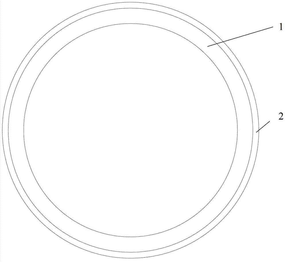
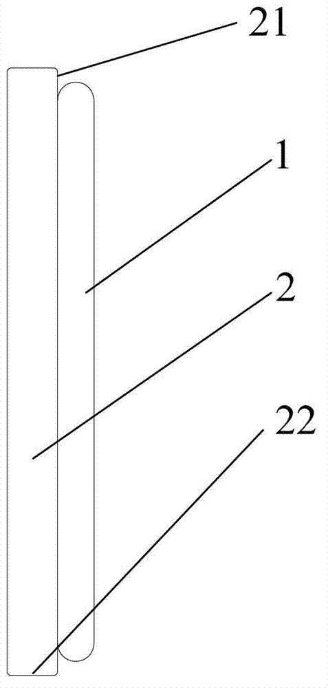
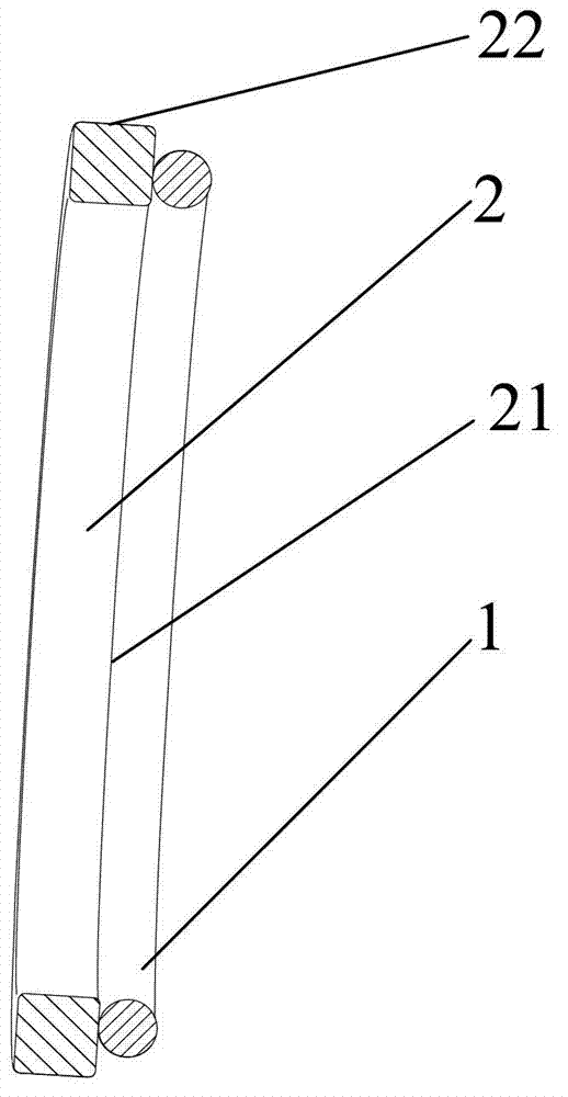

Image

  • Combined sealing part and kinematical sealing structure
  • Combined sealing part and kinematical sealing structure
  • Combined sealing part and kinematical sealing structure

Examples


Embodiment Construction

[0035] In order to understand the above-mentioned purpose, features and advantages of the present invention more clearly, the present invention will be further described in detail below in conjunction with the accompanying drawings and specific embodiments.

[0036] In the following description, many specific details are set forth in order to fully understand the present invention. However, the present invention can also be implemented in other ways different from those described here. Therefore, the protection scope of the present invention is not limited by the specific details disclosed below. EXAMPLE LIMITATIONS.

[0037] The present invention will be further described below in conjunction with the accompanying drawings and embodiments. It should be noted that, in the case of no conflict, the embodiments of the present application and the features in the embodiments can be combined with each other.

[0038] Figure 1 to Figure 3 As shown: the present invention provides a...


PUM


Abstract

The invention provides a combined sealing part, which comprises an elastic support part and an abrasion-proof sealing part matched with the elastic support part. The abrasion-proof sealing part contacts a part to be sealed. The elastic support part supports the abrasion-proof sealing part, so that the abrasion-proof sealing part tightly presses the part to be sealed. The abrasion-proof sealing part is made from a carbon fiber composite material. The abrasion-proof sealing part made from the carbon fiber composite material has the high performance of strong strength, high abrasion resistance, high self lubrication performance, low friction coefficient, small thermal deformation and the like, and is matched with the elastic support part of a certain specification, the combined sealing part can generate pressing force on the abrasion-proof sealing part by using the deformation of the compressed elastic support part, and along with the uniform abrasion of a sealing end face, elastic energy stored by the elastic support part is gradually released, so that uniaxial or radial compensation is realized to realize a kinematical sealing function. The invention also provides a kinematical sealing structure, which has the same advantages.

Description

technical field [0001] The invention relates to the technical field of sealing, in particular to a composite seal and a dynamic seal structure with the composite seal. Background technique [0002] For dynamic seals, floating oil seals and rotary shaft lip seals are two of the sealing forms. [0003] Floating oil seal is a special type of mechanical seal. It is a compact mechanical seal developed to adapt to the harsh working environment. It has strong anti-pollution ability, wear resistance and impact resistance; Compensation, simple structure and other advantages. It is generally composed of a floating ring of ferroalloy material and a matching O-ring. Floating rings are used in pairs: one that rotates with the rotating part and one that is relatively stationary. The sealing principle of the floating oil seal is: the two floating rings are deformed by the axial compression of the O-ring, which produces a pressing force on the sealing end face of the floating ring. With ...

Claims


Application Information

Patent Timeline
Patent Type & Authority Applications(China)
IPC IPC(8): F16J15/20
Inventor 崔书奇杨林鑫
Owner JIKAI EQUIP MFG CO LTD
Learn More