Gradient-index dielectric lens and gradient-index dielectric lens antenna

A technology of dielectric lens antenna and gradient refractive index, which is applied in the field of gradient refractive index dielectric lens and gradient refractive index dielectric lens antenna, can solve the problems of difficult antenna, difficult material to realize, dispersion, etc., and achieve wide operating frequency band, convenient realization and good performance directional effect

Inactive Publication Date: 2014-10-29
SHANGHAI INST OF MICROSYSTEM & INFORMATION TECH CHINESE ACAD OF SCI
View PDF2 Cites 0 Cited by
  • Summary
  • Abstract
  • Description
  • Claims
  • Application Information

AI Technical Summary

Problems solved by technology

Some scholars and researchers have also proposed a method of designing antennas based on the principle of transformation optics, but the general space transformation will cause non-uniformity and anisotropy of electromagnetic parameters, making it difficult to realize the material (see literature: "Planarfocusing antenna design by using coordinate transformation technology,"Applied Physics Letters 91, 253509, 2007)
Although the method of conformal transformation can achieve isotropic electromagnetic parameters, it is generally limited to two-dimensional structures, and the structures often contain regions with a refractive index less than 1, which brings inevitable dispersion, making it difficult for antennas to work in broadband (See literature: "Designing optical elements from isotropic materials by using transformation optics," Physical Review A 81, 033837, 2010)
[0004] So far, there are no examples of applying transformation optics and conformal transformation theory to realize antennas with isotropic materials and capable of broadband operation

Method used


Image

  • Gradient-index dielectric lens and gradient-index dielectric lens antenna
  • Gradient-index dielectric lens and gradient-index dielectric lens antenna
  • Gradient-index dielectric lens and gradient-index dielectric lens antenna

Examples


Embodiment 1

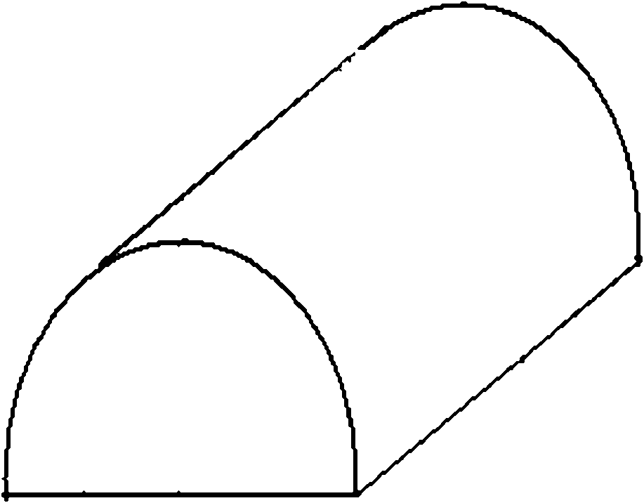
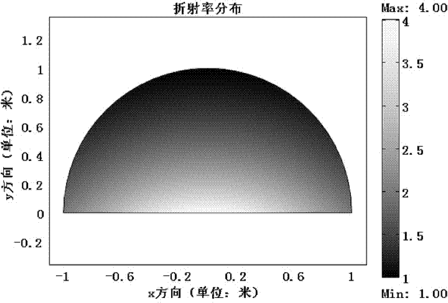
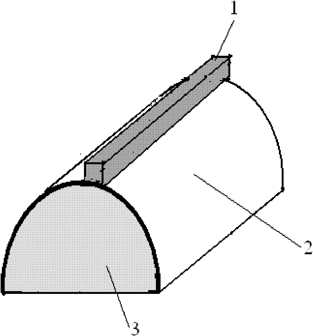
[0022] figure 1 A schematic diagram of a gradient index dielectric lens according to a preferred embodiment of the present invention is shown. The gradient refractive index dielectric lens has a semi-cylindrical shape, and the refractive index distribution of the gradient refractive index dielectric lens satisfies:

[0023] n=k f(s) / [x 2 +(a+y) 2 ],

[0024] Among them, f(s) is any function about the variable s, s=(x 2 +y 2 +a 2 ) / [x 2 +(a+y) 2 ], x is the distance from a point in the gradient index dielectric lens to its principal axis, the principal axis is the plane where the axis line of the semi-cylindrical gradient index dielectric lens is located, and is perpendicular to the rectangular surface, and y is the gradient refraction The distance from a point in the index dielectric lens to the rectangular surface of the gradient index dielectric lens, a is the radius of the gradient index dielectric lens, and k is selected among arbitrary constants based on the mater...

Embodiment 2

[0034] Figure 7 A schematic diagram of a gradient index dielectric lens according to another preferred embodiment of the present invention is shown. The gradient index dielectric lens is in the shape of a hemisphere, and its refractive index distribution satisfies:

[0035] n=k·g(t) / [x 2 +z 2 +(a+y) 2 ],

[0036] where g(t) is any function on the variable t, t=(x 2 +y 2 +z 2 +a 2 ) / [x 2 +z 2 +(a+y) 2 ], y is the distance from a point in the gradient index medium lens to the circular surface of the gradient index medium lens, and x and z are respectively the two distances between a point in the gradient index medium lens and its main axis in the plane where the circular surface is located The projection of the coordinate direction, the main axis is the line connecting the center of the circular surface and the apex of the hemispherical gradient index medium lens, a is the radius of the gradient index medium lens, and k is based on the gradient index medium The mate...


PUM


Abstract

The invention provides a gradient refractive index medium lens and a gradient refractive index medium lens antenna, wherein a refractive index distribution of a semi-cylindrical gradient refractive index medium lens meets a formula disclosed in the specification, and a refractive index distribution of a hemispheric gradient refractive index medium lens meets a formula disclosed in the specification. According to the principle of optical transformation, the refractive index of the semi-cylindrical or hemispheric gradient refractive index medium lens is obtained by adopting conformal transformation calculation and is greater than 1. The semi-cylindrical or hemispheric gradient refractive index medium lens has the advantages of regular distribution, convenience for realization, and wide working band, can not only be used for imaging singly but also be used in the fields of communication and radar by increasing a reflecting surface, and is cooperated with other devices to form an antenna system. According to the gradient reflective index medium lens antenna provided by the invention, the semi-cylindrical or hemispheric gradient refractive index medium lens is used as a main body, thereby having the advantages of good directionality.

Description

technical field [0001] The invention relates to the field of dielectric lenses, in particular to a gradient refractive index dielectric lens and a gradient refractive index dielectric lens antenna. Background technique [0002] Antennas are important devices for directional emission of electromagnetic waves. Common antennas include reflector antennas, horn antennas, and lens antennas. Among them, the structure of the reflector antenna is simple, but the feed source is located in front of the aperture, which will cause a certain shielding of the radiation of the antenna; the pattern of the horn antenna is easy to control, but it often needs to correct the phase when it is used, and it is limited by radio waves or microwaves. frequency band; the directional pattern of the lens antenna is better, but sometimes it is bulky, such as the classic Lunberg lens antenna, the main structure of which is a complete cylinder or spherical lens. [0003] Transformation optics theory is a m...

Claims


Application Information

Patent Timeline
Patent Type & Authority Patents(China)
IPC IPC(8): H01Q15/08H01Q15/23H01Q19/06H01Q19/12H01Q19/15G02B3/00
Inventor 蒋寻涯姚侃梁子贤
Owner SHANGHAI INST OF MICROSYSTEM & INFORMATION TECH CHINESE ACAD OF SCI
Why Eureka
Try Eureka