Steam power plant comprising a tuning turbine

A technology of turbines and turbines, used in machines/engines, mechanical equipment, steam engine installations, etc., can solve problems such as long-term unfavorable operation of efficiency, and achieve the effect of avoiding energy loss and reliable operation.

Inactive Publication Date: 2012-11-07
SIEMENS AG
View PDF4 Cites 3 Cited by
  • Summary
  • Abstract
  • Description
  • Claims
  • Application Information

AI Technical Summary

Problems solved by technology

However, this throttling is disadvantageous in

Method used


Image

  • Steam power plant comprising a tuning turbine
  • Steam power plant comprising a tuning turbine
  • Steam power plant comprising a tuning turbine

Examples


Embodiment Construction

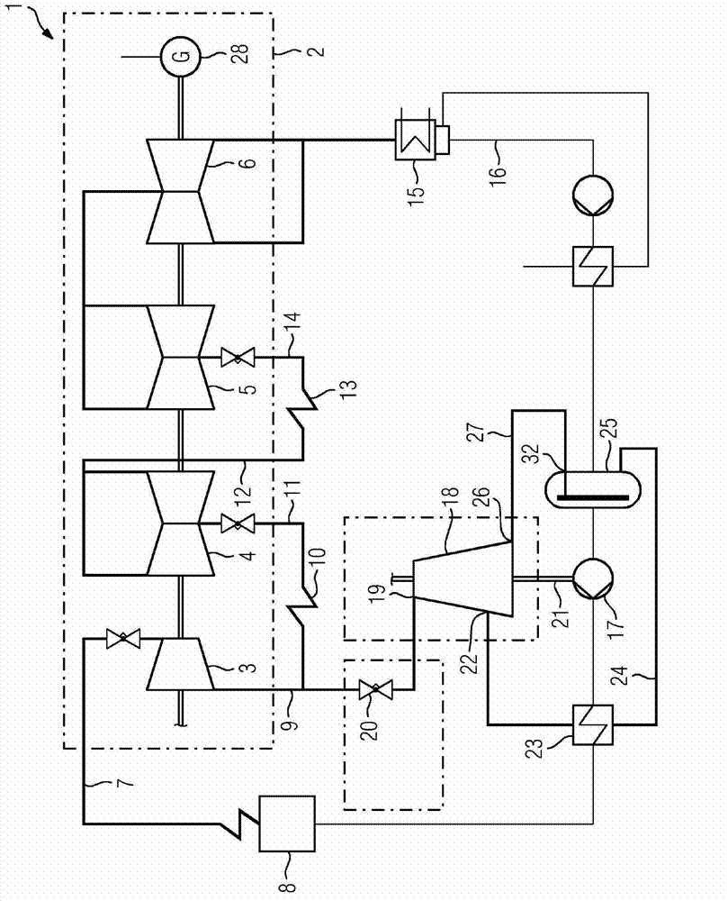
[0021] Figure 1 shows a thermal power plant 1 according to the prior art. The thermal power plant 1 includes a main turbogenerator set 2 , a high-voltage sub-turbine 3 , a first intermediate-pressure sub-turbine 4 , a second intermediate-pressure sub-turbine 5 , and a low-pressure sub-turbine 6 . The high-pressure partial turbine 3 is supplied with live steam via a live steam line 7 by means of a steam generator or boiler 8 . The steam emerging from the high-pressure partial turbine 3 is led in a cold reheater line 9 to a first reheater 10 . The steam is heated up in the first reheater 10 and then passed via the hot reheater line 11 to the first intermediate-pressure partial turbine 4 . The steam flowing out of the first intermediate-pressure partial turbine 4 is introduced into the second reheater 13 via a further cold reheater line 12 . The steam is reheated and passed via a further hot reheater line 14 to the second intermediate-pressure partial turbine 5 . The steam exi...


PUM


Abstract

The invention relates to a steam power plant (1) having a feed pump drive turbine (18) which at the outlet side is connected additionally to a main condenser (15).

Description

technical field [0001] The invention relates to a thermal power station, comprising a main turbine generator set, a condenser, a feed water pump, and an adjustable turbine for driving the feed water pump, wherein the adjustable turbine is configured as a steam turbine, wherein the exhaust port is connected with the steam from the turbine set The delivery portion is fluidly connected. Background technique [0002] Feed water is used in thermal power plants or in power plant processes to be compressed in steam generators and converted into high temperature steam which is then thermally converted in steam main turbine generator sets. The feed water is pumped into the boiler or steam generator against the resistance of the live steam pressure by means of a so-called boiler feed pump. Typically, the boiler feed pump is driven by a steam turbine and is called a feed pump driven turbine (SPAT). When designing the pump drive system described it must be taken into account that the ...

Claims


Application Information

Patent Timeline
IPC IPC(8): F01K9/02F01K17/06
CPCF01K9/02F01K17/06
Inventor 蒂尔曼·弗吕德特勒夫·哈耶迈克尔·韦希松
Owner SIEMENS AG
Why Eureka
Try Eureka