CCD (charge coupled device) angle adjusting device for dentistry CT (Computed Tomography) imaging

An angle adjustment device and CT imaging technology are applied in dental radiology diagnosis, computerized tomography scanner, radiodiagnosis clinical application, etc., which can solve the problems of inaccurate and reliable assurance, poor quality of tomographic images, and lack of fine-tuning, etc., to achieve Low manufacturing cost, improved tomographic image quality, and convenient adjustment

Inactive Publication Date: 2014-02-26
SOUTHEAST UNIV +1
View PDF6 Cites 0 Cited by
  • Summary
  • Abstract
  • Description
  • Claims
  • Application Information

AI Technical Summary

Problems solved by technology

However, the above-mentioned existing dental CT can only roughly adjust the position of the X-ray source and the CCD relative to the patient's head fixation device synchronously with the help of the U-shaped rack, and lacks the independent convenience to fine-tune the three-dimensional angle and displacement of the CCD (or X-ray source). The fine-tuned mechanism device cannot accurately and reliably ensure that the connection line between the X-ray source and the central point of the CCD is perpendicular to the CCD receiving screen and the X-ray source emitting mirror, resulting in poor quality of the finally obtained tomographic image

Method used


Image

  • CCD (charge coupled device) angle adjusting device for dentistry CT (Computed Tomography) imaging
  • CCD (charge coupled device) angle adjusting device for dentistry CT (Computed Tomography) imaging
  • CCD (charge coupled device) angle adjusting device for dentistry CT (Computed Tomography) imaging

Examples


Embodiment

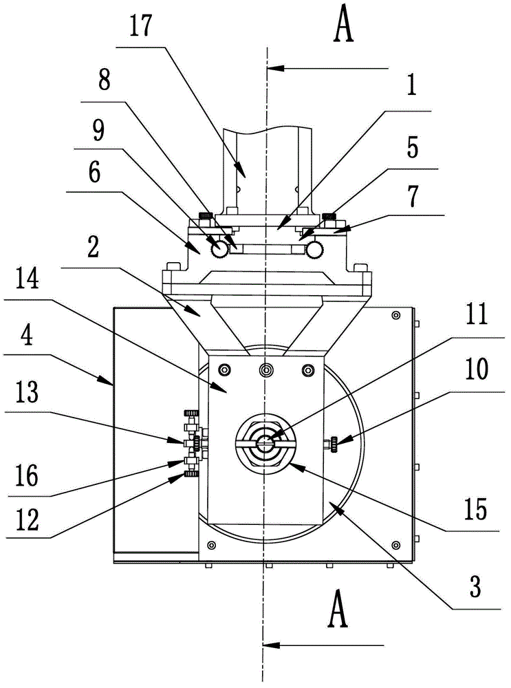
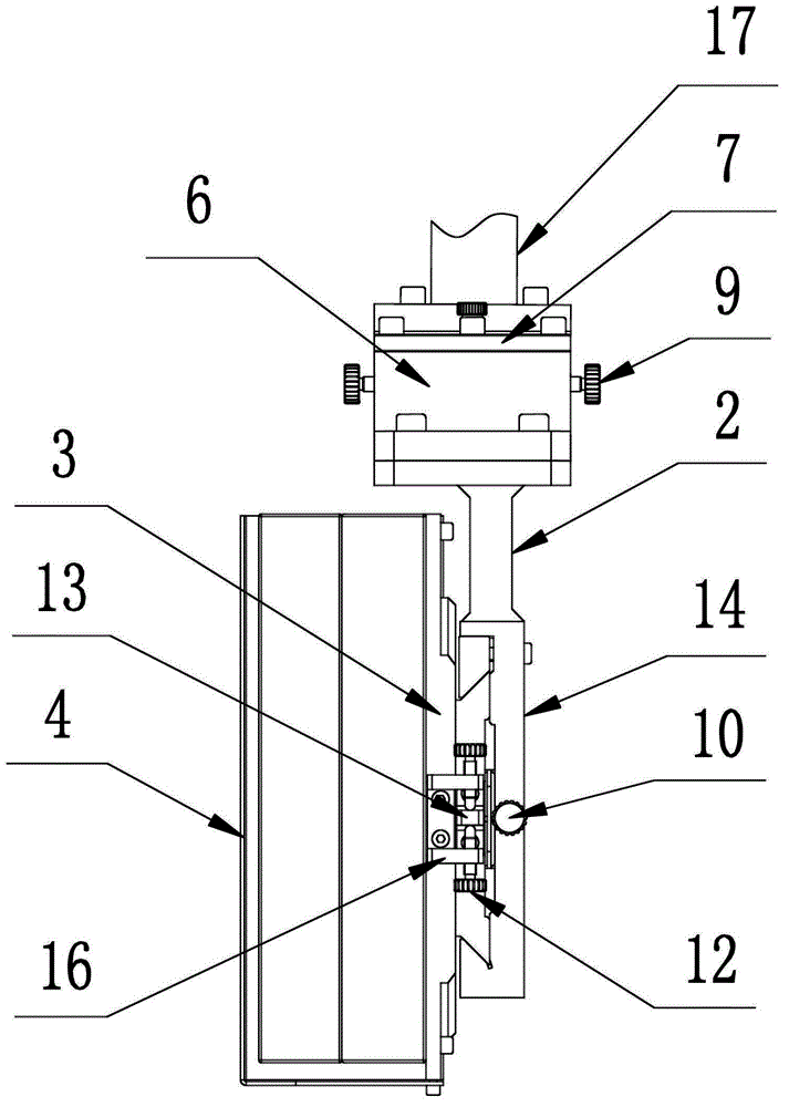
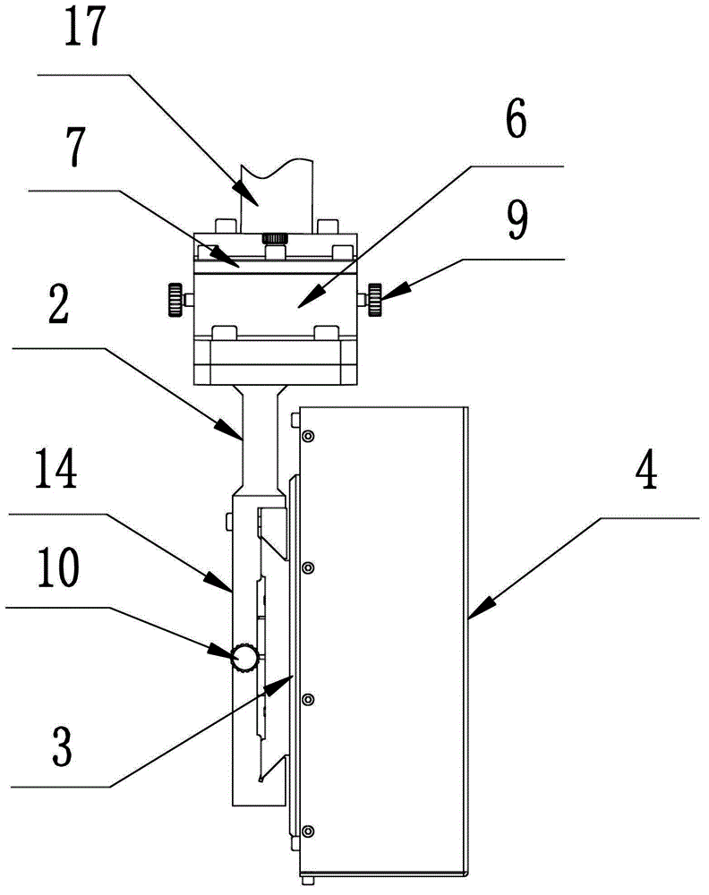
[0025] Example: Combine figure 1 - Figure 6 As shown, this dental CT imaging CCD angle adjustment device provided by the present invention has a U-shaped hanger joint 1, a CCD hanger 2 and a CCD mounting plate 3, and the CCD mounting plate 3 front portion fixes the CCD4 by screws, and the CCD The hanger 2 is connected to the U-shaped hanger joint 1 through a horizontal angle adjustment mechanism that drives it to rotate around the Z axis, and the CCD mounting plate 3 is connected to the CCD hanger through a translation adjustment mechanism that drives it to translate along the X axis. The frame 2 is connected, and the CCD mounting plate 3 is also connected to the CCD hanger 2 by a vertical angle adjustment mechanism that drives it to rotate around the Y axis, wherein the Z axis is perpendicular to the ground, and the Y axis is perpendicular to the CCD receiving screen. The three axes of X, Y, and Z form a space rectangular coordinate system.

[0026] Concrete combination f...


PUM


Abstract

The invention discloses a CCD (charge coupled device) angle adjusting device for dentistry CT (Computed Tomography) imaging. The CCD angle adjusting device comprises a U-shaped hanging rack joint, a CCD hanging rack and a CCD mounting plate, wherein a CCD is fixed at the front part of the CCD mounting plate. The CCD angle adjusting device is characterized in that the CCD hanging rack is connected with the U-shaped hanging rack joint through a horizontal angle adjusting mechanism which drives the CCD hanging rack to rotate by taking a Z axis as a centre; the CCD mounting plate is connected with the CCD hanging rack through a translation adjusting mechanism which drives the CCD mounting plate to translate along an X axis, and meanwhile, the CCD mounting plate is connected with the CCD hanging rack through a vertical angle regulating mechanism which drives the CCD mounting plate to rotate by taking a Y axis as a centre to rotate; and the Z axis is perpendicular to the ground, the Y axis is perpendicular to a CCD receiving screen, and the X,Y and Z axes form a space rectangular coordinate system. The CCD angle adjusting device can be used for performing fine adjustment on the three-dimensional angle and displacement of the CCD so as to ensure that a connecting line of the CCD and the center point of an X ray source is accurately perpendicular to the CCD receiving screen and an X ray source launching mirror face, thereby improving the quality of a tomography image.

Description

technical field [0001] The invention relates to a dental CT imaging CCD angle adjustment device. Background technique [0002] X-ray imaging technology is a very important means of diagnosis and treatment in stomatology. Conventional common X-ray examination techniques (such as apical radiographs, occlusal radiographs, panoramic films, etc.) are easy to operate, have low radiation doses, and are widely used. However, these techniques obtain two-dimensional images, and there are problems such as overlapping structures and image deformation. , can not accurately reflect the three-dimensional information of teeth, periodontal and other structures, and it is often difficult to diagnose difficult diseases. Traditional CT can provide three-dimensional information, but its application in stomatology is limited because of its large radiation dose, high price, and poor clarity of tooth imaging. Compared with these dental imaging techniques, the emerging dental CT (cone beam) has th...

Claims


Application Information

Patent Timeline
Patent Type & Authority Patents(China)
IPC IPC(8): A61B6/14A61B6/03
Inventor 孔凡亮董哥李光罗守华
Owner SOUTHEAST UNIV
Why Eureka
Try Eureka