Machining method for hydraulic excavator walking bar body

A hydraulic excavator and machining technology, applied in metal processing equipment, metal processing mechanical parts, manufacturing tools, etc., can solve the problems of uneven thickness of the connecting plate 1 of the slewing bearing seat, affecting the performance of the whole machine, etc. The effect of size, improvement of processing efficiency, and reduction of manufacturing cost

Inactive Publication Date: 2012-11-14
龙工(上海)挖掘机制造有限公司
View PDF6 Cites 3 Cited by
  • Summary
  • Abstract
  • Description
  • Claims
  • Application Information

AI Technical Summary

Problems solved by technology

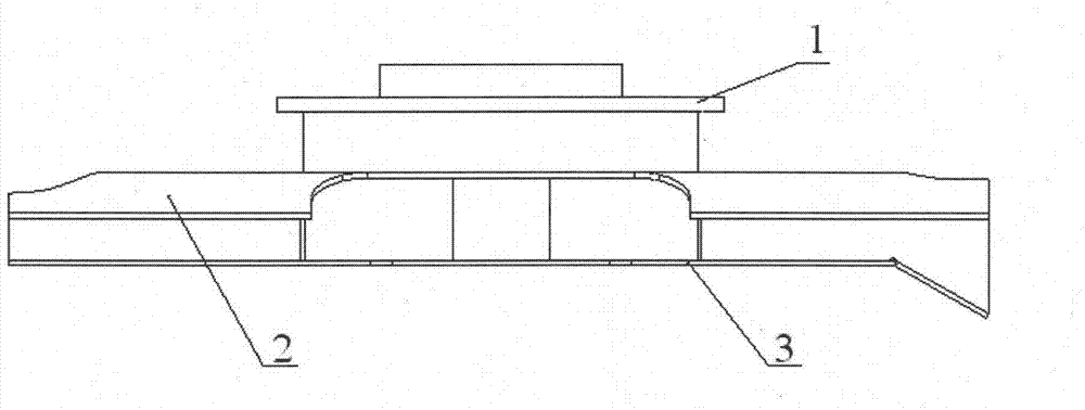
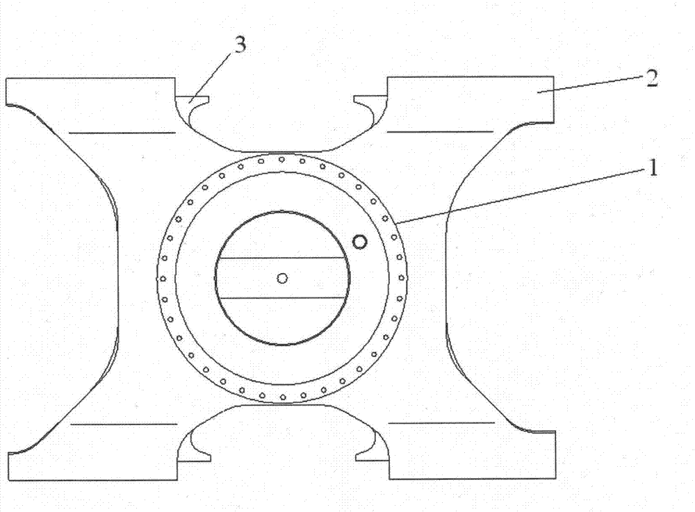
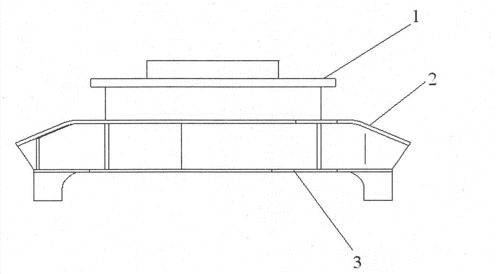
like Figure 1 ~ Figure 3 As shown, the traditional machining process takes the lower cover plate 3 under the upper cover plate 2 of the main body of the walking frame

Method used


Image

  • Machining method for hydraulic excavator walking bar body
  • Machining method for hydraulic excavator walking bar body
  • Machining method for hydraulic excavator walking bar body

Examples


Embodiment Construction

[0023] In order to make the present invention more comprehensible, a preferred embodiment is described in detail below with accompanying drawings.

[0024] A mechanical processing method for the main body of a hydraulic excavator walking frame, using a clamp body, combining Figure 4 ~ Figure 6 , The clip body is divided into left and right parts. Left part: there are four lifting lugs 8 on the left bottom plate 10, which is convenient for hoisting; two linear slide rails 17 are fixed on the left bottom plate 10, and the sliding support 6 is installed on the linear slide rail 17 through the seat slide 18, and the sliding support 6 Connect together with the left V-shaped block 11. The left V-shaped block 11 can slide left and right along the linear slide rail 17 by manual promotion. A first support 9 and a second support 15 are respectively installed on the outer sides of the two linear slide rails 17 . When clamping, the movable crossbeam 5 is supported on the first support...


PUM


Abstract

The invention provides a machining method for a hydraulic excavator walking bar body, which is characterized by comprising the following steps of: putting a fixture body which is not provided with a movable cross beam onto a machine tool workbench by a special fixture body to enable the fixture body to be parallel with the X axis of the machine tool workbench; then, hoisting the walking bar body onto the fixture body; causing the lower plane of a rotary supporting seat connecting plate to be level with the locating surfaces of a left V-shaped block and a right V-shaped block of the fixture body; regulating a first regulation compression bar and a second regulation compression bar to enable the side edge of the lower cover plate of the walking bar body to be parallel with the X axis of the machine tool workbench; then putting the movable cross beam onto the first supporting seat and the second supporting seat, and locking the second regulation compression bar; meanwhile, locking the first regulation compression bar; and finally, machining the walking bar body according to the art work sheet requirement. According to the method provided by the invention, the deficiency in the prior art is overcome, the machining size, the geometric tolerance and the complete machine performance of the walking bar body can be guaranteed. The machining method for the hydraulic excavator walking bar body has the advantages of strong popularity and simple operation step, the machining efficiency is improved, and meanwhile, the excavator manufacture cost is lowered.

Description

technical field [0001] The invention relates to a machining method for a main body of a hydraulic excavator walking frame, and belongs to the technical field of machining technology. Background technique [0002] The main body of the walking frame is an important part of the chassis of the excavator, which is related to the stability of the working state of the excavator. The main factors affecting the stability of the working state of the excavator are the flatness and thickness of the connecting plate of the slewing bearing seat at the top of the main body of the walking frame. Failure to meet the flatness requirements will affect the normal rotation of the excavator, and uneven thickness will cause uneven loads on the locking bolts of the slewing bearing, which will affect its service life. In order to meet the flatness requirements of the slewing bearing seat, the main body of the walking frame needs to be machined. Such as Figure 1 ~ Figure 3 As shown, the traditiona...

Claims


Application Information

Patent Timeline
IPC IPC(8): B23Q3/06B23P15/00
Inventor 郑可文卢恩添唐金平
Owner 龙工(上海)挖掘机制造有限公司
Why Eureka
Try Eureka