Crystal cutting machine

A cutting machine and cutting mechanism technology, applied in the direction of fine working devices, stone processing equipment, manufacturing tools, etc., can solve the problems of unqualified crystals, affecting the cutting efficiency of cutting machines, waste of resources, etc., and achieve simple structure and high cutting efficiency , design reasonable effect

Inactive Publication Date: 2012-11-14
铜陵市琨鹏光电科技有限公司
View PDF7 Cites 5 Cited by
  • Summary
  • Abstract
  • Description
  • Claims
  • Application Information

AI Technical Summary

Problems solved by technology

[0003] If you want to make crystals into various ornaments, you need to cut, polish and polish the crystals. The first thing to do is to cut the large crystals into small pieces, and then polish them to make For jewelry, the requirements for crystal cutting are very strict, and a slight deviation will make the crystal unqualified, resulting in a waste of resources, and the existing crystal cutting machine will produce a large amount of crystal powder during cutting, and the temperature of the cutting machine is high when the cutting machine is working. Too much will affect the cutting efficiency of the cutting machine

Method used


Image

  • Crystal cutting machine
  • Crystal cutting machine

Examples


Embodiment Construction

[0013] In order to make the technical means, creative features, goals and effects achieved by the present invention easy to understand, the present invention will be further described below in conjunction with specific illustrations.

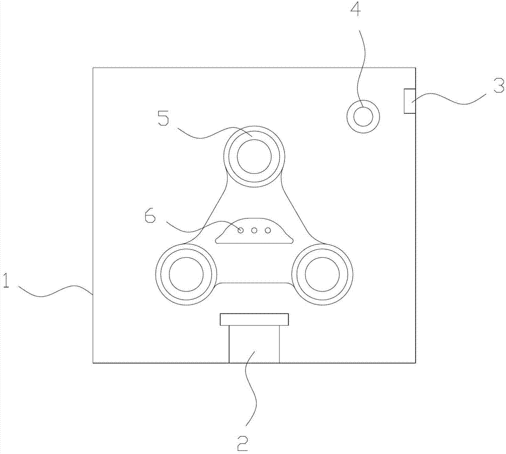
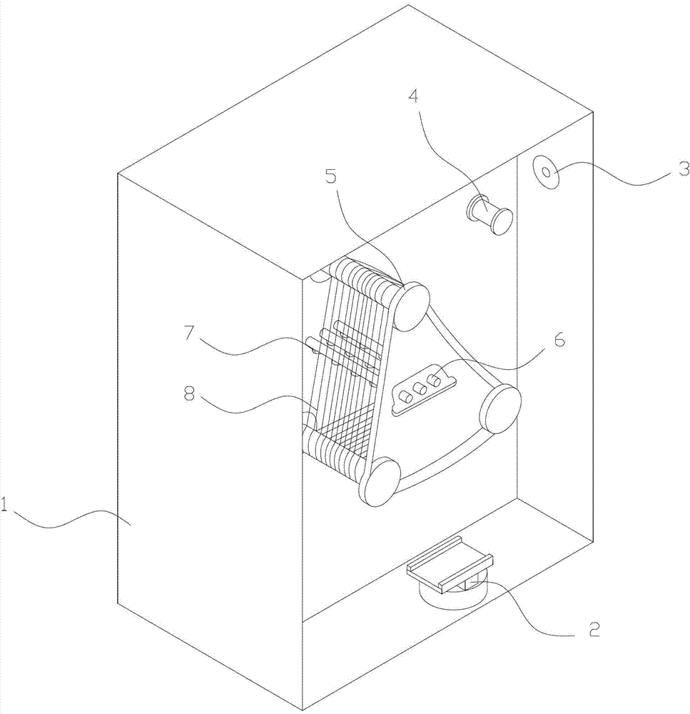
[0014] A crystal cutting machine, the main body of which is a box 1, the bottom of the box 1 is provided with a feeding mechanism 2 that moves up and down, the side is provided with a wire outlet 3, the front is provided with a cutting mechanism and a steel wire transition roller 4, the cutting mechanism It includes a roller shaft 5 and a sand conveying pipe 6 designed in the shape of a character. The steel wire 8 is wrapped on the roller shaft 5. The sand conveying pipe 6 is arranged in the middle of the roller shaft. The sand conveying pipe 6 is equipped with a sandblasting nozzle 7. Three tubes 6 are provided.

[0015] After the steel wire 8 comes out of the wire discharge port 3, it passes through the steel wire transition roller 4 and trans...


PUM


Abstract

The invention relates to a crystal cutting machine, and belongs to the field of crystal cutting equipment. A main body of the crystal cutting machine is a box body, and the crystal cutting machine is characterized in that a feeding mechanism moving up and down is arranged on the bottom surface of the box body, a paying-off port is formed on the side surface of the box body, and a cutting mechanism and a steel wire transitional roller are arranged on the front surface of the box body; the cutting mechanism comprises roll shafts which are designed in a shape of a Chinese character:pin:, and three sand conveying pipes; steel wires wrap on the roll shafts; and the sand conveying pipes are arranged among the roll shafts, and a sand nozzle is arranged on each sand conveying pipe. The crystal cutting machine is simple in structure and reasonable in design; the steel wires come out of a wire outlet and then are transited to the roll shafts through the transitional roller; when the roll shafts rotate, the steel wires are wrapped on the roll shafts circle by circle; and during the cutting, a material plate to which crystals are adhered is fixed on the feeding mechanism, and when the roll shafts rotate, the feeding mechanism moves upwards, the sand nozzles spray out mortar which falls on the steel wires which reciprocate at a high speed, and the steel wires together with the mortar attached to the steel wires are used for grinding the crystals, so that the aim of the cutting is fulfilled, and the cutting efficiency is high.

Description

technical field [0001] The invention relates to the technical field of crystal cutting equipment, in particular to a crystal cutting machine. Background technique [0002] Crystal is a colorless transparent quartz crystal mineral. Its main chemical is silica, which can be regarded as "born in the same mother's womb" as ordinary sand. When the silicon dioxide crystallizes perfectly, it is a crystal; because of the hardness and beauty of the crystal, there are more and more ornaments made of crystal. [0003] If you want to make crystals into various ornaments, you need to cut, polish and polish the crystals. The first thing to do is to cut the large crystals into small pieces, and then polish them to make For jewelry, the requirements for crystal cutting are very strict, and a slight deviation will make the crystal unqualified, resulting in waste of resources, and the existing crystal cutting machine will produce a large amount of crystal powder during cutting. Too much wi...

Claims


Application Information

Patent Timeline
Patent Type & Authority Applications(China)
IPC IPC(8): B28D5/04
Inventor 陈子荣
Owner 铜陵市琨鹏光电科技有限公司
Why Eureka
Try Eureka