Long-distance pulse compression and short-distance pulse envelope detection delay measurement combined distance measuring method

A pulse compression and pulse envelope technology, which is applied in the field of long-distance pulse compression and short-range pulse envelope detection delay measurement combined with ranging, can solve problems such as difficulty, real-time impact of the system, and increased hardware complexity. Achieve the effect of improving ranging accuracy, simple implementation and high real-time performance

Inactive Publication Date: 2012-11-14
SHANGHAI RADIO EQUIP RES INST
View PDF2 Cites 7 Cited by
  • Summary
  • Abstract
  • Description
  • Claims
  • Application Information

AI Technical Summary

Problems solved by technology

In some microwave radar systems that require high-precision ranging, especially in short-distance measurements, the pulse compression method for ranging to achieve high measurement accuracy requires that the transmitted chirp signal has an extremely wide bandwidth, that is, an extremely narrow pulse. Wide, but in the actual hardware system, it is difficult to generate such a signal, and it is difficult to mix it to a higher radio frequency and transmit it
Moreover, for a signal with a wider bandwidth, it is also necessary to use a higher sampling rate for A / D sampling when receiving, which increases the complexity of the hardware
In addition, when the sampling range gate is wide, the calculation amount of the pulse compression ranging method is relatively large, which has a certain impact on the real-time performance of the system
Therefore, it is difficult to achieve high ranging accuracy by using traditional pulse compression methods.

Method used


Image

  • Long-distance pulse compression and short-distance pulse envelope detection delay measurement combined distance measuring method
  • Long-distance pulse compression and short-distance pulse envelope detection delay measurement combined distance measuring method
  • Long-distance pulse compression and short-distance pulse envelope detection delay measurement combined distance measuring method

Examples


Embodiment Construction

[0025] According to Figure 1- Figure 4 , specifically explain the preferred embodiment of the present invention.

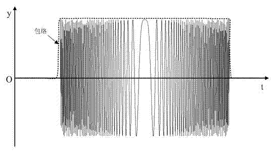
[0026] As shown in Figure 1, the present invention provides a method for combining long-distance pulse compression and short-distance pulse envelope detection delay measurement, including the following steps:

[0027] Step 1, transmit signal;

[0028] When transmitting, the microwave source 1 generates an intermediate frequency chirp signal, mixes with the local oscillator signal to the radio frequency, generates the required pulse width and power after modulation and power amplification, and finally radiates out from the antenna 5 through the circulator 4;

[0029] Step 2, receiving the signal;

[0030] When receiving, the echo signal received by the microwave radar enters the receiving channel through the circulator 5, and after being strobed and amplified by the switch, it is mixed with the local oscillator signal and reduced to the intermediate frequency, a...


PUM


Abstract

The invention discloses a long-distance pulse compression and short-distance pulse envelope detection delay measurement combined distance measuring method. The method comprises the following steps of during long-distance range measurement, measuring a distance by adopting the conventional pulse compression method, wherein a selected signal bandwidth can meet the requirement of the long-distance distance measuring accuracy; and during short-distance measurement, extracting linear frequency modulated signal envelope by adopting an envelope detection method after switching a received echo signal to a medium frequency through down-conversion in a receiver, finding a delay point on a detection envelop front edge by adopting a constant-ratio time point discriminant approach, so as to generate a delay pulse, and comparing differential delay between the delay pulse and a transmission detection pulse signal to obtain high-accuracy target distance information. According to the method, the distance measuring accuracy is increased effectively.

Description

technical field [0001] The present invention relates to a microwave radar high-precision ranging method, in particular to a distance measuring method combined with long-distance pulse compression and short-distance pulse envelope detection delay measurement, which can be used for ground-based radar, vehicle-mounted radar, ship-borne Radar, spaceborne radar and other microwave radar signal processing that require ranging. Background technique [0002] With the development of modern electronic warfare and information warfare, higher and higher requirements are put forward for microwave radar performance indicators such as operating range, resolution and measurement accuracy. In order to improve the detection ability of the radar system and increase the operating distance, it can only be achieved by increasing the time width of the transmitted pulse when the peak power of the system equipment is limited. The distance resolution of the radar depends on the bandwidth of the sign...

Claims


Application Information

Patent Timeline
Patent Type & Authority Applications(China)
IPC IPC(8): G01S13/08
Inventor 黄琼邹波吉峰
Owner SHANGHAI RADIO EQUIP RES INST
Why Eureka
Try Eureka