Electric energy router

A router and power technology, applied in circuit devices, electrical components, digital transmission systems, etc., can solve the problems of complex bidirectional power flow, influence of power grid operation and management, weak information and control functions of grid-connected inverters, etc., to improve stability. performance, reliability, ease of monitoring and management, and full and reasonable utilization

Active Publication Date: 2012-11-14
TIANJIN UNIV
View PDF4 Cites 25 Cited by
  • Summary
  • Abstract
  • Description
  • Claims
  • Application Information

AI Technical Summary

Problems solved by technology

However, there are still the following problems to be solved urgently in the utilization of distributed energy: 1) The existence of a large number of distributed renewable energy causes complex two-way power flow between the large power grid and various distributed power sources, which affects the operation of the power grid. 2) Distributed power generation has obvious uncertainties in power supply capacity and power quality due to the influence of regions and weather, and existing technologies and equipment cannot guarantee that these power energies will be fully utilized
On the one hand, a large amount of distributed electric energy is directly connected to the grid without passing through the "electrical access node" stipulated in the IEEE 1547 and IEC 61850 standards, which brings many difficulties to the monitoring and management of the grid. Traditional protection and metering devices also do not support On the other hand, the existing grid-connected inverters are relatively weak in terms of information and control functions, resulting in the inability of unified and effective management of distributed energy

Method used


Image

  • Electric energy router
  • Electric energy router
  • Electric energy router

Examples


Embodiment Construction

[0022] The working principle of the present invention will be described in detail below in conjunction with the accompanying drawings.

[0023] The invention provides an electric energy routing device capable of realizing grid-connected management of distributed power sources and optimal matching operation of distributed power sources and loads.

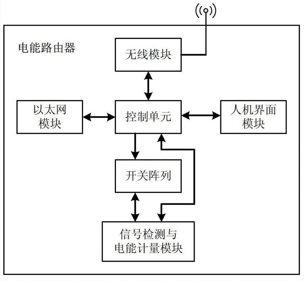
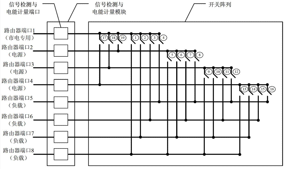
[0024] see figure 1 , the hardware of the power router in this embodiment includes a control unit, a wireless module, a signal detection and power metering module, a switch array, and a router port, and also includes some wireless modules, Ethernet modules, human-machine interface modules, etc. (the Ethernet module and the man-machine interface module are not included in the necessary technical features of the power router of the present invention). The power port is divided into a special port for mains power and a common power port, the latter is used to connect the power supply port of the distributed power supply or the battery ...


PUM


Abstract

The invention belongs to the field of the distribution-type renewable power supply utilization in an intelligent power grid and relates to an electric energy router which comprises a control unit, a wireless module, a signal detection and electric energy metering module, a switch array and a router port, wherein the router port comprises a power supply port and a load port; the power supply port comprises a power supply port dedicated for the mains supply and a plurality of common power supply ports; the control unit carries out the optimal matching on the power supply and the load according to the electric energy quality information of a power supply connected with a common power supply port and the electricity utilization characteristics of the load connected with the load port, wherein the electric energy quality information is collected by a signal detection and electric energy metering port of the power supply or is obtained by a wireless module, and the electricity utilization characteristics are collected by a load signal detection and electric energy metering port or is obtained by the wireless module; and matched power supplies and loads can be connected or switched through the switch array. According to the electric energy router, the on-grid management of various distribution-type power supplies and the optimal load matching can be realized.

Description

technical field [0001] The invention belongs to the field of utilization of distributed renewable power sources in smart grids, and relates to a control device capable of realizing grid-connected management of distributed power sources and optimal matching with loads. Background technique [0002] In the future smart grid, there will be a large number of distributed renewable energy sources (photovoltaic, wind power, fuel cells, etc.), which will be used to save energy, reduce emissions, and alleviate peak power consumption. However, there are still the following problems to be solved urgently in the utilization of distributed energy: 1) The existence of a large number of distributed renewable energy causes complex two-way power flow between the large power grid and various distributed power sources, which affects the operation of the power grid. 2) Due to the influence of regions and weather, distributed power generation has obvious uncertainties in power supply capacity an...

Claims


Application Information

Patent Timeline
Patent Type & Authority Applications(China)
IPC IPC(8): H02J13/00H04L12/56H04L45/60
CPCY04S40/126Y02E60/7853Y02E60/00
Inventor 刘迎澍李冰杨凯新
Owner TIANJIN UNIV
Why Eureka
Try Eureka