Valve for a magnetorheological liquid

A magneto-rheological fluid and magnetic field technology, applied in the valve field of magnetorheological fluid, can solve the problems of no energy saving, less energy saving, etc., and achieve the effect of energy saving and life extension

Active Publication Date: 2012-11-14
INVENTUS ENG
View PDF7 Cites 11 Cited by
  • Summary
  • Abstract
  • Description
  • Claims
  • Application Information

AI Technical Summary

Problems solved by technology

[0009] However, significant energy consumption also occurs, for example, when the through-flow resistance of the valve changes continuously or in each case different states exist for a longer period of time
In this or other cases, the different states may also present the same entitlement, so that a permanent magnet for specifying a preferred operating point in the valve provides only little or no energy savings

Method used


Image

  • Valve for a magnetorheological liquid
  • Valve for a magnetorheological liquid
  • Valve for a magnetorheological liquid

Examples


Embodiment Construction

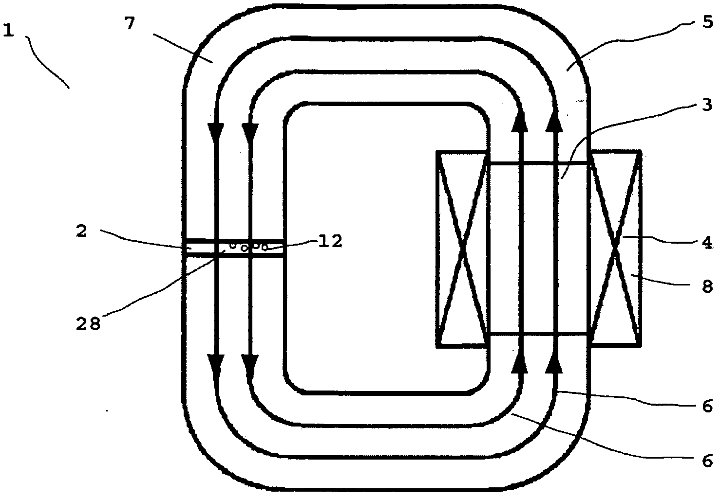
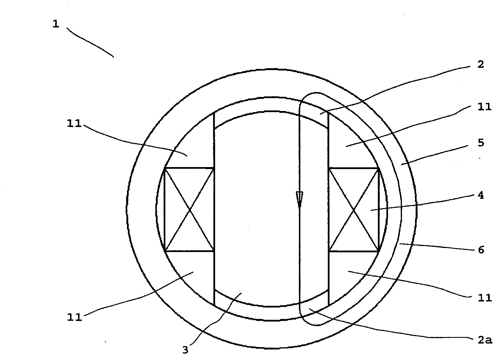
[0120] figure 1 A highly simplified schematic diagram of a valve 1 according to the invention is shown. The magnetic flux lines 6 described as vectors have been illustrated in order to clarify the function more clearly.

[0121] In the region of the flow tube 2 the magnetic field 9 of the magnet or magnetic device 7 can act on the magnetorheological fluid 12 . In the magnetic field 9, the particles 30 of the magnetorheological fluid 12 are positioned and form chains, resulting in an increase in the viscosity of the fluid. The viscosity can be set as desired within a wide range by means of the strength of the effective magnetic field 9 .

[0122] The configurable shear stress of the magnetorheological fluid 12 also depends on the magnetic field 9 . If the pressure differential in the flow tube 2 is below this shear stress, flow is prevented. Up to this limit, the valve 1 blocks the through-flow of the magnetorheological fluid 12 .

[0123] The flow tube 2 forms a closed ma...


PUM


Abstract

A valve for a magnetorheological liquid comprises a duct through which the magnetorheological liquid can flow and which can be exposed to a variable magnetic field such that the flow resistance of the duct can be set using the magnetic field in the duct. The magnetic field can be lastingly generated using a magnet device made at least in part of magnetically hard material. The magnetization of the magnet device can be lastingly modified by a magnetic pulse of a magnetic field generation device in order to lastingly change the magnetic field in the duct and thus the flow resistance of the duct. A valve of the invention requires energy only to change settings while a specific setting can be lastingly maintained without supplying energy.

Description

technical field [0001] The invention relates to a valve for magneto-rheological fluids, which valve has a flow tube for which the flow of magnetorheological fluid through the flow tube can be varied by means of a magnetic field acting on the flow tube. The flow resistance through the flow tube and thus the throughflow through the valve is expediently influenced by the magnetic field. Background technique [0002] Magnetorheological fluids generally comprise a suspension of small ferromagnetic particles, such as carbonyl iron powder, finely distributed in a carrier fluid. These particles typically have a diameter between 0.1 and 50 microns, and form a chain structure under the action of a magnetic field, so that the viscosity of the magnetorheological fluid is significantly enhanced under the action of the magnetic field. In this case, the change in viscosity occurs very rapidly, on the scale of a few milliseconds or less, and is completely reversible. [0003] The main adv...

Claims


Application Information

Patent Timeline
Patent Type & Authority Applications(China)
IPC IPC(8): F16F9/53F16K13/10F16K31/06F16K31/08
CPCF16K31/0675F16K13/10F16F9/537F16K31/082Y10S137/909Y10T137/2082
Inventor 斯特凡·巴特洛格于尔根·波赛尔赫尔诺特·埃尔森索恩
Owner INVENTUS ENG
Why Eureka
Try Eureka