
Radiation source, lithographic apparatus and device manufacturing method

A technology of lithography equipment and radiation source, applied in the field of radiation source, which can solve the problems of difficult removal of tin, loss of reflectivity, damage to multi-layer coatings, etc.

Inactive Publication Date: 2012-11-14
ASML NETHERLANDS BV
View PDF6 Cites 11 Cited by
  • Summary
  • Abstract
  • Description
  • Claims
  • Application Information

AI Technical Summary

Problems solved by technology

Any tin deposited on the mirror can cause a significant loss of reflectivity and on the other hand damage the multilayer coating
This deposited tin is difficult to remove

Method used


Image

  • Radiation source, lithographic apparatus and device manufacturing method
  • Radiation source, lithographic apparatus and device manufacturing method
  • Radiation source, lithographic apparatus and device manufacturing method

Examples


Embodiment Construction

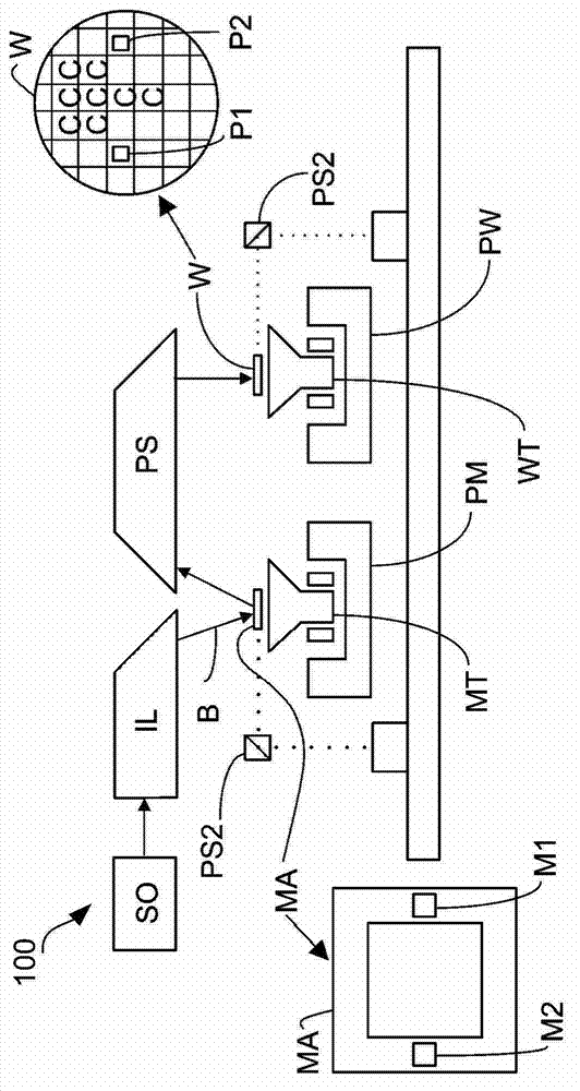
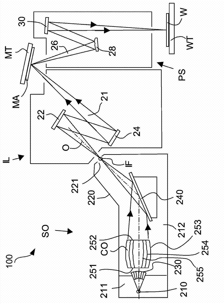
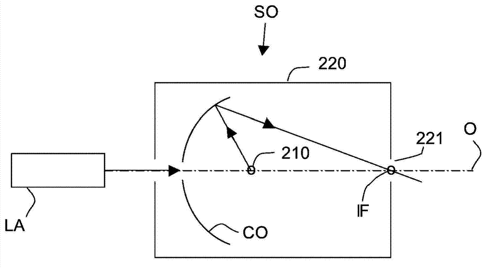
[0033] This specification discloses one or more embodiments that incorporate the features of this invention. The disclosed embodiments are merely exemplary of the invention. The scope of the present invention is not limited to these disclosed embodiments. The invention is defined by the appended claims.

[0034] The described embodiments, and references in this specification to "one embodiment," "an embodiment," "exemplary embodiment," etc., indicate that the described embodiments may include a particular feature, structure, or characteristic. , but each embodiment may not necessarily include the specific feature, structure or characteristic. Additionally, such terms are not necessarily referring to the same embodiment. Furthermore, when a specific feature, structure or characteristic is described in conjunction with an embodiment, it should be understood that such feature, structure or characteristic can also be implemented in combination with other embodiments with the kn...


PUM


Abstract

A radiation source for generating extreme ultraviolet radiation for a lithographic apparatus has a debris mitigation device comprising a nozzle arranged at or near an intermediate focus (IF) of the beam of radiation. The nozzle serves to direct a flow of gas (330) towards the radiation source or collector optic in order to deflect particulate debris (43) emitted by the radiation source.

Description

[0001] Cross References to Related Applications [0002] This application claims priority to US Provisional Applications 61 / 313,452 and 61 / 348,477, filed March 12, 2010, and May 26, 2010, respectively, which are hereby incorporated by reference in their entirety. technical field [0003] The invention relates to a radiation source, in particular a radiation source for lithography, a lithographic apparatus and a method for manufacturing a device. Background technique [0004] A lithographic apparatus is a machine that applies a desired pattern to a substrate, usually a target portion of the substrate. A lithographic apparatus may be used, for example, in the manufacture of integrated circuits (ICs). In this case, a patterning device, alternatively referred to as a mask or reticle, may be used to generate the circuit pattern to be formed on the individual layers of the IC. The pattern can be transferred onto a target portion (eg, comprising a portion, one or more dies) on a ...

Claims


Application Information

Patent Timeline
Patent Type & Authority Applications(China)
IPC IPC(8): G03F7/20G02B5/00G21K1/08
CPCH05G2/003G03F7/70933H05G2/008G02B19/0028G03F7/70916G02B5/00G02B19/0047G02B19/0095G02B19/00G03F7/70908G02B19/0023G03F7/20G21K1/08
Inventor D·兰贝特斯基V·班尼恩E·鲁普斯特拉A·亚库宁
Owner ASML NETHERLANDS BV
Learn More