Automatic die filling fixture for IMD sheet material

A technology of jigs and sheets, applied in the direction of coating, etc., can solve the problems of low production efficiency, many operators, production chaos, etc., and achieve the effect of saving labor costs and high degree of automation

Inactive Publication Date: 2012-11-21
DONGGUAN MEMTECH ELECTRONICS MEMTECH ELECTRONICS PRO
View PDF3 Cites 2 Cited by
  • Summary
  • Abstract
  • Description
  • Claims
  • Application Information

AI Technical Summary

Problems solved by technology

[0004] This method of IMD sheet production is the most widespread and common factory configuration method, however, this kind of production has a low degree of automation and low production efficiency
In addition, many operators are required

Method used


Image

  • Automatic die filling fixture for IMD sheet material
  • Automatic die filling fixture for IMD sheet material
  • Automatic die filling fixture for IMD sheet material

Examples


Embodiment Construction

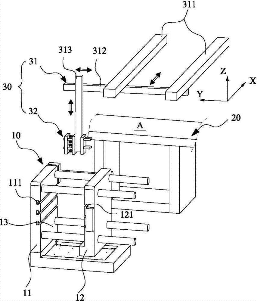
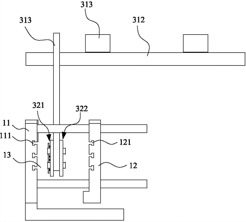
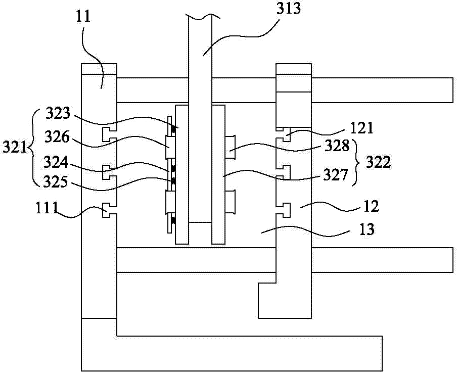
[0032] Please refer to Figure 1 to Figure 3 Shown, it has shown the concrete structure of preferred embodiment of the present invention, comprises IMD injection mold 10, feed fixture 20 and manipulator 30, and this manipulator 30 is used for IMD material part is automatically packed in IMD injection mold 10, And at the same time, the formed IMD sheet is taken out from the IMD injection mold 10 and placed on the feeding jig 20 .

[0033] Wherein, the IMD injection mold 10 comprises a fixed platen 11 and a movable platen 12, the fixed platen 11 and the movable platen 12 are vertically arranged, a mold cavity 13 is formed between the two, and the movable platen 12 is provided with a first mold The cavity 111 and the fixed template 11 are correspondingly provided with a second cavity 121, and the first cavity 111 and the second cavity 121 are facing each other on the left and right. The forming principle of the IMD injection mold 10 is as follows: by automatically feeding the IM...


PUM


Abstract

The invention discloses an automatic die filling fixture for an IMD sheet material. The fixture comprises an IMD injection mold and a mechanical arm; the IMD injection mold comprises a fixed mold plate and a movable mold plate, the fixed mold plate and the movable mold plate are vertically arranged, a die cavity is formed between the fixed mold plate and the movable mold plate, a first mold cavity is arranged on the movable mold plate, a second mold cavity is arranged on the fixed mold plate, and the first mold cavity and the second mold cavity are respectively located at a left side and a right side and are opposite to each other; the mechanical arm comprises a three-dimensional freely-movable mechanism and an automatic suction means installed at the lower part of the three-dimensional freely-movable mechanism, the automatic suction means comprises a first suction mechanism used for delivering an IMD material member to the fixed mold plate and a second suction mechanism used for taking out an IMD sheet material obtained after injection molding from the movable mold plate, the first suction mechanism and the second suction mechanism are such arranged that the back of the first suction mechanism faces the back of the second suction mechanism, and when the automatic suction means stretches into the die cavity of the IMD injection mold under driving of the three-dimensional freely-movable mechanism, the first suction mechanism is opposite to the fixed mold plate and the second suction mechanism is opposite to the movable mold plate.

Description

technical field [0001] The invention relates to the technology in the field of IMD sheet forming equipment, in particular to an automatic mold loading fixture for IMD sheets. Background technique [0002] IMD (In Mold Decoration) technology is currently the most popular surface decoration technology in the world. Using surface-hardened IMD sheet, middle printing pattern layer, back injection molding layer and ink in between, it can make the product surface more wear-resistant and avoid being scratched , and can keep the color bright and not easy to fade for a long time. [0003] At present, the production of IMD sheets is a semi-automatic mode, in which the delivery of materials and finished products produced by IMD is completed by manually pushing the transport trolley. When manufacturing, a plurality of operators need to be arranged next to each IMD forming mold, and the first operator takes out the material from the transport trolley, and manually implements the loading ...

Claims


Application Information

Patent Timeline
IPC IPC(8): B29C45/14
Inventor 黄伟
Owner DONGGUAN MEMTECH ELECTRONICS MEMTECH ELECTRONICS PRO
Why Eureka
Try Eureka