Disturbing device for conveying materials, pneumatic conveying device and material conveying method

A pneumatic conveying and material technology, applied in the direction of conveyors, transportation and packaging, conveying bulk materials, etc., can solve the problem that the uniformity of falling of anti-blocking materials cannot be solved at the same time, and achieve the effect of preventing accumulation and improving uniformity

Active Publication Date: 2012-11-21
BEIJING GUODIAN FUTONG SCI & TECH DEV +1
View PDF10 Cites 3 Cited by
  • Summary
  • Abstract
  • Description
  • Claims
  • Application Information

AI Technical Summary

Problems solved by technology

[0005] In summary, the material conveying device in the prior art cannot simultaneously solve the problems of anti-clogging and uniformity of material falling

Method used


Image

  • Disturbing device for conveying materials, pneumatic conveying device and material conveying method
  • Disturbing device for conveying materials, pneumatic conveying device and material conveying method
  • Disturbing device for conveying materials, pneumatic conveying device and material conveying method

Examples


Embodiment 1

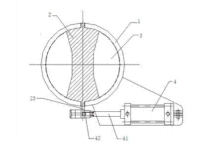
[0040] Such as image 3 and Figure 4 As shown, the disturbance device for material transportation provided by this embodiment includes a housing 1 having a housing inlet and a housing outlet; it also includes a disturbance component 2 installed in the housing Inside the body 1, a material circulation channel 3 is formed with the inner wall of the housing 1; the driving mechanism is connected with the disturbance component 2, and the flow cross-sectional area of ​​the material circulation channel 3 is changed by controlling the disturbance component 2, thereby changing The falling speed of the material, thereby preventing the material from caking and clogging.

[0041] It should be noted that, in the present invention, there are various ways to change the flow cross-sectional area of ​​the material flow channel 3 by controlling the disturbing member 2, which can be a rotation method or a parallel movement method. The ways in which the disturbance member 2 changes the flow cr...

Embodiment 2

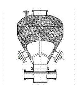
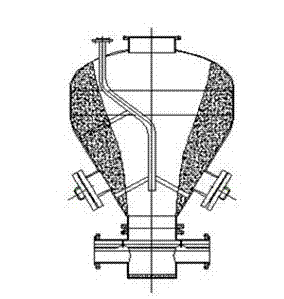
[0051] Such as Figure 8 As shown, the present embodiment provides a pneumatic conveying device, comprising a conveying tank 6, having a discharge port arranged at the bottom of the conveying tank 6, a feed valve arranged on the conveying tank 6, extending into the The air blowing device in the delivery tank 6, and the disturbance device arranged at the bottom of the delivery tank 6, the disturbance device includes a housing 1, and the housing 1 has a housing inlet and a housing outlet, so The feed port of the disturbance device communicates with the discharge port of the delivery tank 6, the mixer, the mixer has a mixer feed port and a mixer discharge port, and the mixer feed port is connected to the shell The body discharge port is connected; the disturbance device also includes a disturbance component 2, which is installed in the housing 1 and forms a material flow channel 3 with the inner wall of the housing 1; and a driving mechanism to drive the disturbance The componen...

Embodiment 3

[0064] This embodiment provides a method for conveying materials using the pneumatic conveying device described in Embodiment 2, including the following steps:

[0065] A. Open the blowing device to blow compressed air into the delivery tank 6;

[0066] B. Open the feed valve to transport the material into the delivery tank 6, and the material flows to the mixer 7 along the material circulation channel 3 under the action of compressed air and its own gravity;

[0067] C. When the pressure detection device detects that the pressure in the delivery tank 6 is less than the predetermined pressure, control the action of the disturbance device, so that the cross-sectional area of ​​the material circulation channel 3 changes the falling speed of the material, preventing The material arches and clogs.

[0068] As a preferred implementation manner, in this embodiment, the cross-sectional area of ​​the material circulation channel 3 is changed by changing the relative positional relati...


PUM


Abstract

The invention provides a disturbing device for conveying materials, a pneumatic conveying device with the disturbing device and a material conveying method. The disturbing device comprises a shell, and further comprises a disturbing part and a driving mechanism, wherein the shell is provided with a shell material inlet and a shell material outlet; the disturbing part is mounted in the shell; a material flowing passage is formed between the disturbing part and the inner wall of the shell; and the driving mechanism is used for driving the disturbing part to act so as to change flowing section area of the material flowing passage. Through the adoption of the material conveying device provided by the invention, blockage can be prevented and the materials can fall off uniformly.

Description

technical field [0001] The invention relates to a disturbance device for material conveying, a pneumatic conveying device and a material conveying method, belonging to the field of pneumatic conveying. Background technique [0002] Pneumatic conveying is a technology that uses airflow with a certain speed and pressure to convey solid materials in pipelines. It is currently widely used in the transportation of mineral powder, molding sand, fly ash, etc. [0003] Pneumatic conveying exerts pneumatic force on the conveyed material through the airflow, thereby pushing the material to move and realize the conveyance of the material. When the speed of the conveyed material is too high, the material quickly falls from the conveying tank and enters the outlet of the mixer. The air force provided by the pneumatic conveying device is limited. Therefore, when the falling speed of the material is too high, the material will easily block the outlet of the mixer, resulting in the failure ...

Claims


Application Information

Patent Timeline
Patent Type & Authority Applications(China)
IPC IPC(8): B65G53/40B65G53/66
Inventor 丁岩峰刘新华李新生范力遥孙奉昌李子甲章新波张春霞杜岩
Owner BEIJING GUODIAN FUTONG SCI & TECH DEV
Why Eureka
Try Eureka