
New utilization process for catalytic cracking slurry oil

A catalytic cracking oil slurry and catalytic oil slurry technology, which is applied in the petroleum industry, liquid carbon-containing fuel, hydrocarbon distillation, etc., can solve the problems of narrow application range, complex process route, single product, etc., and achieve good economic and social benefits , optimize the effect of rational use

Active Publication Date: 2012-11-21
CHINA PETROLEUM & CHEM CORP
View PDF8 Cites 19 Cited by
  • Summary
  • Abstract
  • Description
  • Claims
  • Application Information

AI Technical Summary

Problems solved by technology

The process route of this method is complex and requires high equipment. In addition to the oil slurry vacuum distillation unit, a set of visbreaking unit is also required for its implementation; the scope of application of this method is narrow, and the blending components are limited to deoiled hard asphalt; And the product is single

Method used


Image

  • New utilization process for catalytic cracking slurry oil
  • New utilization process for catalytic cracking slurry oil
  • New utilization process for catalytic cracking slurry oil

Examples


Embodiment 1

[0035] The light oil slurry A obtained by controlling the maximum temperature of the distillation outlet to 370°C has a yield of about 12%, and its quality indicators are shown in the following table:

[0036]

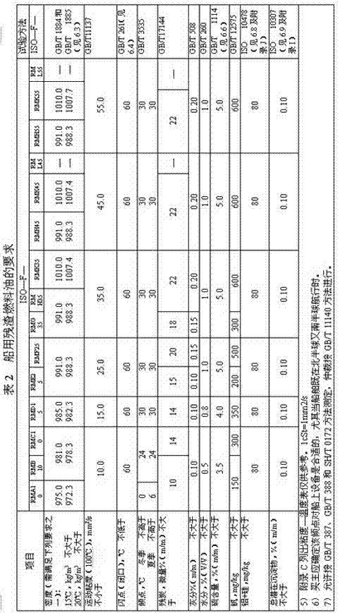
[0037] Comparing the indicators of the People's Republic of China national standard ZB / T 17411-1998 marine fuel oil shown in Table 2, it can be seen that the light oil slurry A meets the marine residual fuel oil indicator of model RMA10.

Embodiment 2

[0039] The light oil slurry B obtained by controlling the maximum temperature of the distillation outlet to 390°C has a yield of about 30%, and its quality indicators are shown in the following table:

[0040]

[0041] Comparing the indicators of the People's Republic of China national standard ZB / T 17411-1998 marine fuel oil shown in Table 2, it can be seen that the light oil slurry B meets the marine residual fuel oil indicator of model RMA10.

Embodiment 3

[0043] The light oil slurry C obtained by controlling the maximum temperature of the distillation outlet to 420°C has a yield of about 50%, and its quality indicators are shown in the following table:

[0044]

[0045] Comparing the indicators of the People's Republic of China national standard ZB / T 17411-1998 marine fuel oil shown in Table 2, it can be seen that the light oil slurry C meets the marine residual fuel oil indicators of model RMD15.


PUM

PropertyMeasurementUnit
Solidifying pointaaaaaaaaaa

Abstract

The present invention discloses a new utilization process for catalytic cracking slurry oil. According to the process, catalytic slurry oil is subjected to vacuum distillation to obtain light slurry oil and topped slurry oil, wherein a distillation outlet temperature is 360-480 DEG C; physical and chemical indicators of the light slurry oil are detected, and are compared with marine fuel oil standards, wherein the light slurry oil meeting the standards is directly adopted as marine residual fuel oil, or a diesel component is adopted to blend to meet the standards so as to adopt the light slurry oil as marine distillate fuel oil, or a residue oil component is adopted to blend to meet the standards so as to adopt the light slurry oil as marine residual fuel oil. The marine fuel oil standards are the national standards ZB / T17411-1998. The diesel component is one or a plurality of materials selected from normal pressure second side oil, normal pressure third side oil, a catalytic diesel and a hydrogenated diesel, and is blended into the light slurry oil, wherein the use amount of the diesel component is 30-95% of the total amount. The residue oil component is one or a plurality of materials selected from vacuum residue oil, viscosity reduction residue oil and deoiled asphalt, and is blended into the light slurry oil, wherein the use amount of the residue oil component is 5-85% of the total amount. The new process of the present invention has characteristics of simple process, wide raw material, and product diversification.

Description

technical field [0001] The invention relates to the field of petrochemical industry, in particular to a new process for utilizing catalytic cracking oil slurry. Background technique [0002] Catalytic cracking oil slurry refers to the material extracted from the bottom of the distillation tower of the catalytic cracking unit, which is usually called catalytic oil slurry in the oil refining industry. Usually, the oil slurry is used for returning to catalytic cracking for further cracking, blending as boiler fuel or other fuels, as raw material for coking, as raw material for asphalt, etc. Since the main component of oil slurry is condensed-ring aromatics with short side chains, the main contribution to catalytic cracking is low-value coke and gas. Even if the liquid product is obtained, it is aromatics with poor properties and poor stability, so oil slurry is not catalytic cracking. Good material for installation. The oil slurry contains catalyst dust, and it is used as boi...

Claims


Application Information

Patent Timeline
IPC IPC(8): C10G7/00C10L1/04
Inventor 康伟青蔡智黄建华徐燕平徐盛虎郑京禾
Owner CHINA PETROLEUM & CHEM CORP
Learn More