Adjusting device and method for injection flow rate of evaporative cooling tower during dry converter dedusting

A converter dry dust removal, evaporative cooling technology, applied in the direction of manufacturing converters, improving process efficiency, improving energy efficiency, etc., can solve problems such as reducing the service life of equipment, reducing the effect of electric field dust removal, and valve actions cannot keep up with changes. Achieve the effect of prolonging the service life

Inactive Publication Date: 2012-11-21
WISDRI ENG & RES INC LTD
View PDF3 Cites 7 Cited by
  • Summary
  • Abstract
  • Description
  • Claims
  • Application Information

AI Technical Summary

Problems solved by technology

However, since the amount of sprayed water is related to the temperature of the converter flue gas, in the early stage of blowing, the temperature of the flue gas is rising rapidly, so the corresponding cooling water flow setting value is also increasing, but if the regulating valve is put into PID automatic control too early , because the set value changes too fast, the valve action cannot keep up with the changing temperature, and if the open-loop control is adopted in the initial stage and set at a fixed valve position, there may be too much water in the initial stage, but not enough water in the later stage Happening
[0003] If there is too much water in the initial stage and the temperature of the airflow is low, the generated dust will be compacted, which will affect the dust removal efficiency of the dust collector. What is more serious is to aggravate the corrosion of the equipment in the electric field and reduce the service life of the equipment; , causing additional burning loss of the equipment and reducing the dust removal effect of the electric field

Method used


Image

  • Adjusting device and method for injection flow rate of evaporative cooling tower during dry converter dedusting
  • Adjusting device and method for injection flow rate of evaporative cooling tower during dry converter dedusting

Examples


Embodiment Construction

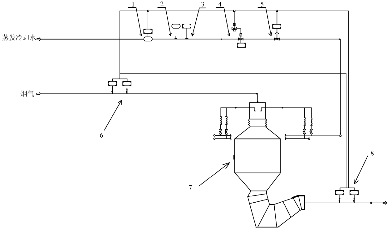
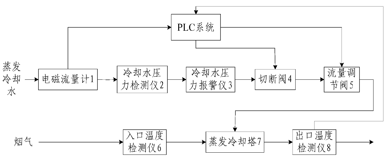
[0015] Such as figure 1 As shown, the converter dry dedusting evaporative cooling tower spray water adjustment device of the present invention comprises an evaporative cooling tower 7, and the cooling tower has two input ports and an output port, wherein one of the input ports is connected to the flue gas channel, and on the flue gas channel An inlet temperature detector 6 is provided, and the other input port is connected to the evaporative cooling water channel, and the evaporative cooling water channel is provided with an electromagnetic flowmeter 1, a cooling water pressure detector 2, a cooling water pressure alarm 3, a shut-off valve 4 and A flow regulating valve 5; the output port is connected to an outlet temperature detector 8.

[0016] The method for adjusting the amount of sprayed water in the converter dry dedusting evaporative cooling tower of the present invention is divided into two processes: at the initial stage of blowing, open-loop control of the opening of ...


PUM

PropertyMeasurementUnit
densityaaaaaaaaaa

Abstract

The invention discloses an adjusting device and an adjusting method for the injection flow rate of an evaporative cooling tower during dry converter dedusting and especially relates to control of the injection flow rate of an evaporative cooling tower during dry converter dedusting in the industries of metallurgy steel-making. The device comprises an electromagnetic flowmeter, a cooling water pressure detector, a cooling water pressure alarm instrument, a shut-off valve, a flow control valve, an evaporative cooling tower, an inlet temperature detector and an outlet temperature detector. The adjusting method comprises open loop control in an initial stage of converting and closed loop PID control when the temperature of flue gas tends to be stable. Open loop control realizes signal transmission mainly through connection of control signals of the electromagnetic flowmeter, the shut-off valve, the flow control valve and the outlet temperature detector with a PLC system to so as to allow water flow to vary with the temperature of flue gas, and therefore, water supply in the whole control process is balanced and the purpose of automatic control and adjustment of the injection flow rate is achieved.

Description

technical field [0001] The invention relates to a device and a method for adjusting the water spray volume of a converter dry dedusting evaporative cooling tower, in particular to the control of the water spray volume of a converter dry dedusting evaporative cooling tower in the metallurgical steelmaking industry. Background technique [0002] In the metallurgical and steelmaking industry, the core of dry dust removal is temperature control. There is a flow regulating valve on the water supply pipe of the converter dry dedusting evaporative cooler, and it starts to be put into operation after the converter blows oxygen. The general control method is to first set the regulating valve to a preset opening, and then wait for a period of time. Switch to PID control. However, since the amount of sprayed water is related to the temperature of the converter flue gas, in the early stage of blowing, the temperature of the flue gas is rising rapidly, so the corresponding cooling water...

Claims


Application Information

Patent Timeline
Patent Type & Authority Applications(China)
IPC IPC(8): C21C5/40C21C5/46
CPCY02P10/25
Inventor 吉青
Owner WISDRI ENG & RES INC LTD
Why Eureka
Try Eureka