High-speed railroad shoulder and drainage structure

A technology for high-speed railways and road shoulders, which is applied to roads, buildings, ballast layers, etc., and can solve the problems of irregular cutting, poor water seepage and drainage in cable troughs, which affect the stability and settlement of filling subgrades, and difficulty in cutting.

Inactive Publication Date: 2012-11-21
CHINA RAILWAY ERYUAN ENG GRP CO LTD
View PDF7 Cites 13 Cited by
  • Summary
  • Abstract
  • Description
  • Claims
  • Application Information

AI Technical Summary

Problems solved by technology

[0003] The technical problem to be solved by the present invention is to provide a high-speed railway shoulder and drainage structure to solve the problem of grading gravel cutting at the position of the cable trough on the high-speed railway shoulder and the effective discharge of water seepage in the cable trough, avoiding the cutting of the grading gravel at the position of the cable trough on the road shoulder Difficulty and irregular cutting, as well as poor drainage of cable troughs affect the stability of the filled subgrade and settlement problems

Method used


Image

  • High-speed railroad shoulder and drainage structure
  • High-speed railroad shoulder and drainage structure

Examples


Embodiment Construction

[0011] The present invention will be further described below in conjunction with the drawings and embodiments.

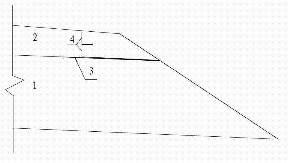
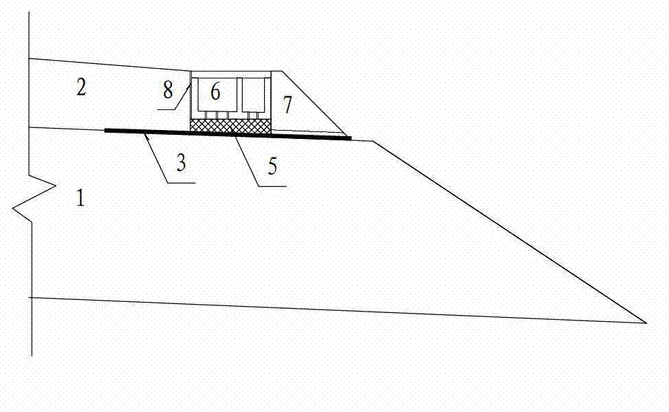
[0012] Reference figure 1 , The high-speed railway shoulder and drainage structure of the present invention includes a base bed 1 filled on the ground or on the basic body of the road, a surface layer 2 of the base bed filled on top of the bottom 1 of the base bed, and a cable trench 5 arranged at the shoulder of the railway , The composite geomembrane 3 is laid between the bottom layer 1 of the foundation bed and the surface layer 2 of the foundation bed, and the geotextile 4 is laid in layers within the surface layer 2 of the foundation bed. Reference figure 2 , The bottom of the cable trough 5 is provided with a water-permeable material 6, and the outer side is provided with a roadbed shoulder 7; an asphalt wood board 8 is provided between the cable trough and the surface 2 of the subgrade. The top of the bottom layer 1 of the foundation bed is provided with a dra...


PUM


Abstract

The invention relates to a high-speed railroad shoulder and drainage structure, which aims to solve the problems of graded broken stone cutting at the position of a high-speed railroad shoulder cable channel and effective draining of seepage water in the cable channel, avoid problems of difficult cutting and irregular cutting of graded broken stones at the position of the railroad shoulder cable channel as well as the problem that stability and sedimentation of the filling subgrade are influenced by poor seepage water drainage in the cable channel. The high-speed railroad shoulder and drainage structure comprises a subgrade bed bottom layer filled on the ground or a subgrade body, a subgrade bed surface layer filled on the top of the subgrade bed bottom layer and a cable channel arranged at a railroad shoulder. A composite geomembrane is laid between the subgrade bottom layer and the subgrade bed surface layer, and a geotextile is laid on the internal layer of the subgrade bed surface layer; a seepage material is arranged at the bottom part of the cable channel, and the outer side of the cable channel is provided with a subgrade protection shoulder. An asphalt board is arranged between the cable channel and the subgrade bed surface layer.

Description

Technical field [0001] The invention relates to a high-speed railway, in particular to a high-speed railway shoulder and drainage structure. Background technique [0002] High-speed railway cable troughs in China are all placed on the shoulder of the roadbed. It is necessary to cut the graded gravel on the surface shoulder part of the filled high-speed railway subgrade bed and then place the cable trough. Because the graded gravel is dense and high in strength, cutting is difficult and difficult. It is easy to cause the adjacent uncut part of the graded rubble to loosen; after the cable trough is placed, the gap between the cable trough and the inner subgrade bed surface and the gap between the cable trough cover plate cause rainwater to infiltrate into the cable trough; the traditional cable trough is on the outside Setting the drain hole, the location of the drain hole of the cable trough and the drain hole of the subgrade shoulder are difficult to correspond or the correspondi...

Claims


Application Information

Patent Timeline
Patent Type & Authority Applications(China)
IPC IPC(8): E01B1/00
Inventor 姚裕春朱颖李安洪孙莺庞应刚曾永红徐骏龚建辉赵青海李井元陈丽
Owner CHINA RAILWAY ERYUAN ENG GRP CO LTD
Why Eureka
Try Eureka