Turbine engine using compressed air as working energy

A technology for compressed air and engine, applied in the field of piston turbine engine, can solve the problems of no industrialized application example of complete device design, poor work reliability, low work efficiency, etc., and achieve less heat loss, high safety, and structure. simple effect

Inactive Publication Date: 2012-11-21
彭学军
View PDF11 Cites 12 Cited by
  • Summary
  • Abstract
  • Description
  • Claims
  • Application Information

AI Technical Summary

Problems solved by technology

[0009] The currently known aerodynamic engines are all developed on local or key components. So far, there is no complete set of device design and successful industrial application examples. flaws caused by immaturity

Method used


Image

  • Turbine engine using compressed air as working energy
  • Turbine engine using compressed air as working energy
  • Turbine engine using compressed air as working energy

Examples


Embodiment Construction

[0046] In order to enable those skilled in the art to better understand the solution of the present invention, the present invention will be further described in detail below in conjunction with the accompanying drawings and specific embodiments.

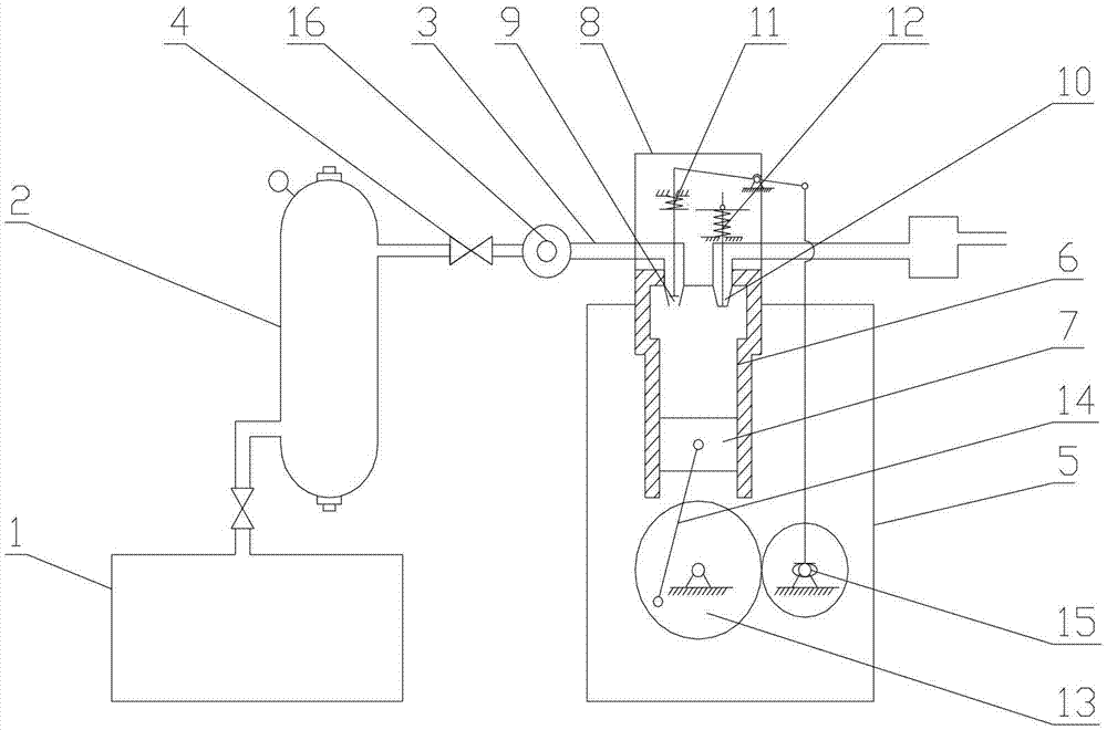
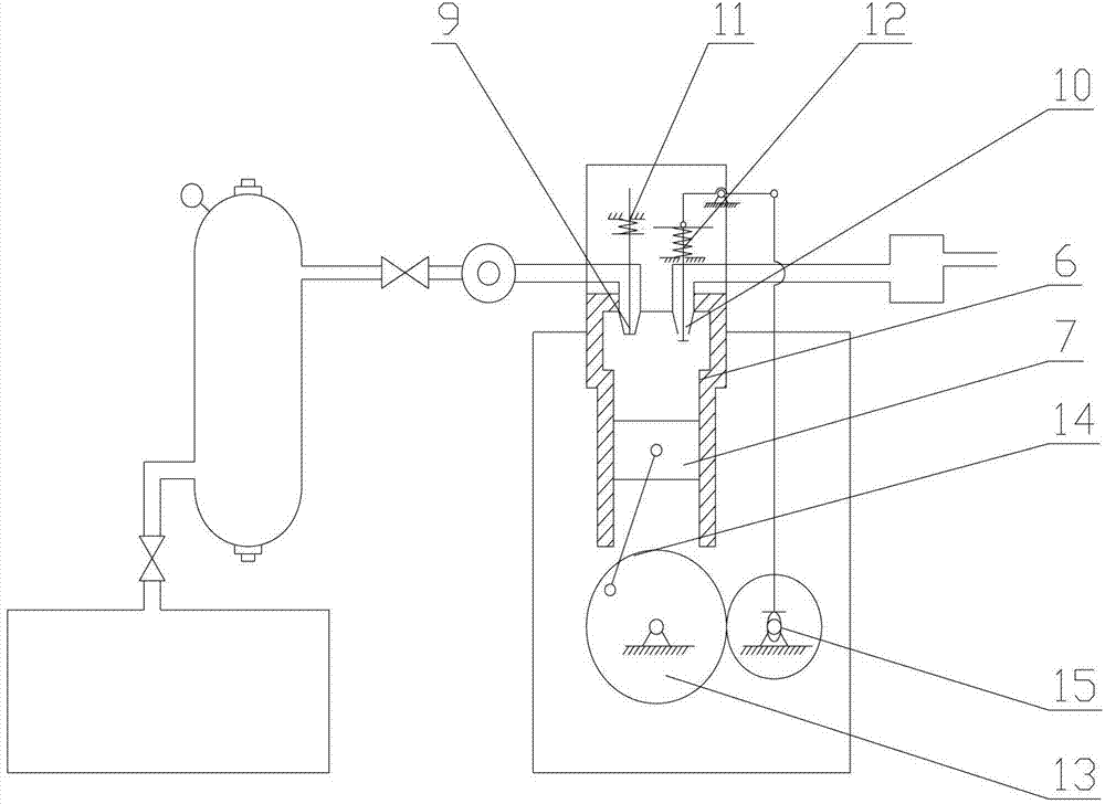
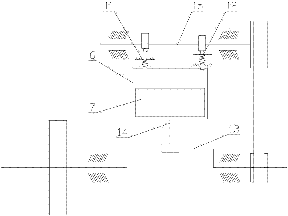
[0047] Please refer to figure 1 , figure 2 , image 3 , figure 1 It is a structural schematic diagram of a specific embodiment of the turbo engine provided by the present invention, in which the engine is in the intake power stroke; figure 2 It is a structural schematic diagram of a specific embodiment of the turbo engine provided by the present invention, in which the engine is in the exhaust stroke; image 3 for figure 1 Schematic diagram of the working principle of the turbine engine shown.

[0048] In a specific embodiment, the turbine engine using compressed air as the functional source provided by the present invention includes four subsystems of air source, control, work, and lubrication attached to the same body, as w...


PUM


Abstract

The invention discloses a turbine engine using compressed air as a working energy. The turbine engine comprises a gas source system, a controlling system, a working system and a lubricating system, as well as a gas distributing mechanism, a transmission mechanism and an auxiliary mechanism, wherein the gas source system is supplied with a gas source by an air compressor and/or a compressed air storage container and is connected in series by pipelines; the control system is arranged between the gas source system and the working system and comprises an electronic monitoring device and a control valve; the working system comprises a shell and at least a group of air cylinder and piston arranged inside the shell; and the lubricating system comprises a lubricating oil duct, an engine oil pump, an engine oil filter and a valve arranged in the air cylinder. By using the compressed air as a working medium, the engine can create a working environment and condition that an absolute pressure difference between the pressure of the compressed air source and that of the non-working air in a working chamber exists. On the basis of further optimizing the structure of working and transmission systems, potential of the compressed air can be efficiently and adequately converted into turbine mechanical energy, and furthermore, mechanical work is output externally.

Description

technical field [0001] The invention relates to the technical field of engines, in particular to a piston turbine engine using compressed air as a working medium. Background technique [0002] In order to effectively deal with the energy crisis brought about by the exhaustion of fossil energy, many countries are seeking alternatives to fossil energy, such as wind energy, nuclear energy, solar energy, and biofuels. However, whether it is non-renewable or renewable energy, a large part must be converted into electricity for utilization. Therefore, the main form of energy in the future will still be electricity. [0003] At present, electric energy storage technologies in the world can be roughly divided into physical energy storage and chemical energy storage. Among them, physical energy storage includes pumped water energy storage, compressed air energy storage, flywheel energy storage, phase change energy storage, etc. Chemical energy storage includes lead-acid batteries,...

Claims


Application Information

Patent Timeline
Patent Type & Authority Applications(China)
IPC IPC(8): F01B9/02F01B25/10
CPCF01B17/02F01B25/02
Inventor 彭学军
Owner 彭学军
Why Eureka
Try Eureka