Light beam shaping and cutting system for stage luminaire and stage luminaire

A cutting system and lighting technology, applied in the direction of optics, optical components, light source fixation, etc., can solve the problems of limited operating freedom of cutting components, difficult to cut components, fast cutting speed, complex structure, etc., to achieve convenient transportation and storage placement, Good cutting strobe effect, simple assembly process

Active Publication Date: 2012-11-21
GUANGZHOU FINEART LIGHTING
View PDF6 Cites 5 Cited by
  • Summary
  • Abstract
  • Description
  • Claims
  • Application Information

AI Technical Summary

Problems solved by technology

[0004] In the prior art, the transmission structure of the cutting assembly generally adopts a transmission structure such as a screw or a screw. Although this structure can realize the purpose of driving the cutting assembly, it has the following defects: (1) The transmission speed is too slow, and it is difficult to Make the cutting components obtain a faster cutting speed, thereby affecting the beam cutting effect of the stage lamps and stage performances; (2) It takes up a lot of space, so that the entire lamp is relatively large and cumbersome; (3) The movement is not flexible , the operating freedom of the cutting components is limited, so that some beam shape effects cannot be obtained by cutting
Other types of transmission structures are often complex in structure and occupy a large maneuvering space, which cannot meet the needs of reducing the size of the lamp and realizing fast cutting and flexible movement at the same time.

Method used


Image

  • Light beam shaping and cutting system for stage luminaire and stage luminaire
  • Light beam shaping and cutting system for stage luminaire and stage luminaire
  • Light beam shaping and cutting system for stage luminaire and stage luminaire

Examples


Embodiment Construction

[0033] The structure and working principle of the present invention will be described in detail below with reference to the accompanying drawings.

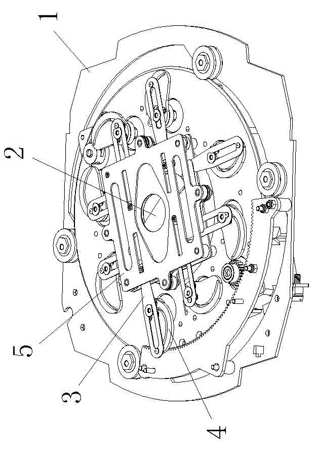
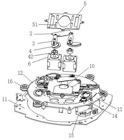
[0034] refer to Figure 1-3 As shown, the beam forming and cutting system for stage lamps and lanterns of the present invention includes:

[0035] The bracket 1 extends along the light beam direction of the stage lamp and is fixedly connected with the shell of the stage lamp;

[0036] A cutting mechanism composed of four groups of cutting blades 2, each group of cutting blades is respectively arranged in a different plane perpendicular to the light beam and can move along the plane where it is located;

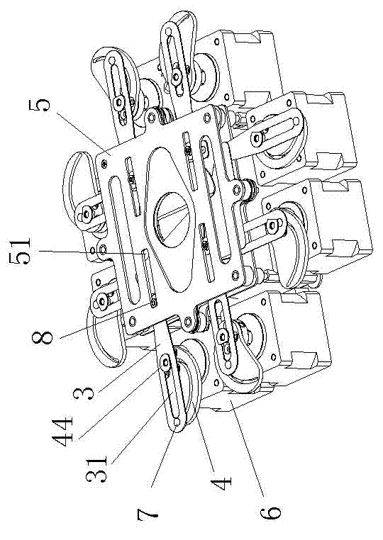
[0037] Four pairs of actuators, each pair of actuators are connected to a group of corresponding cutting blades 2; any one of the actuators includes a driving motor 6 and a transmission mechanism, and the driving motor 6 is fixed on the bracket 1.

[0038] Such as Figure 2 to Figure 5 As shown, any transmission mechanism inclu...


PUM


Abstract

The invention discloses a light beam shaping and cutting system for a stage luminaire. The light beam shaping and cutting system for the stage luminaire comprises a support, a plurality of sets of cutting blades and a plurality of pairs of actuating mechanisms, wherein all sets of cutting blades are respectively arranged in different planes which are orthogonal with light beams and can move alonginside the planes; each pair of actuating mechanisms is connected with one set of corresponding cutting blades; each actuating mechanism comprises a drive motor and a transmission mechanism; the drive motors are arranged on the support; each transmission mechanism comprises a push rod, a cam and a guide plate; the cams are fixedly connected with the corresponding drive motors; one ends of the push rods are movably connected with the corresponding cutting blades; the other ends of the push rods are movably connected with the corresponding cams; and the guide plates are arranged on the support.The cams, the push rods and the guide plates are matched to convert the rotary motion of the output shaft of the corresponding drive motor into the linear motion of the corresponding push rod, so that a higher cutting speed can be obtained. Meanwhile, a cam and push rod mechanism is simple in structure, small in size and reasonable in layout.

Description

technical field [0001] The invention belongs to the technical field of stage lamps, and in particular relates to a light beam forming and cutting system for stage lamps and a stage lamp applying the cutting system. Background technique [0002] In the field of stage technology, a beam shaping component is usually arranged between the light source of the stage lamp and the light-emitting objective lens to intercept the beam so as to obtain a beam with a specific cross-section. [0003] The cutting component is one of the typical beam shaping components, which can be used to obtain a beam of arbitrary shape profile, and can also adjust the size of the beam. In stage performances, the lighting engineer will cut the light spots projected by the lamps into various shapes according to the needs of the plot or scene. [0004] In the prior art, the transmission structure of the cutting assembly generally adopts a transmission structure such as a screw or a screw. Although this stru...

Claims


Application Information

Patent Timeline
Patent Type & Authority Applications(China)
IPC IPC(8): F21V14/00G02B27/09
Inventor 刘建华
Owner GUANGZHOU FINEART LIGHTING
Why Eureka
Try Eureka