
Apparatus for charging raw material in sintering machine

A technology of raw materials and guide grooves, applied in the direction of furnace types, furnaces, lighting and heating equipment, etc., can solve the problems of not being able to apply scrapers, etc., and achieve the effect of improving strength

Active Publication Date: 2014-11-05
NIPPON STEEL CORP
View PDF7 Cites 0 Cited by
  • Summary
  • Abstract
  • Description
  • Claims
  • Application Information

AI Technical Summary

Problems solved by technology

As mentioned above, it cannot be applied to the scraper configured to slide while the bottom is floating from the surface of the guide groove

Method used


Image

  • Apparatus for charging raw material in sintering machine
  • Apparatus for charging raw material in sintering machine
  • Apparatus for charging raw material in sintering machine

Examples


Embodiment Construction

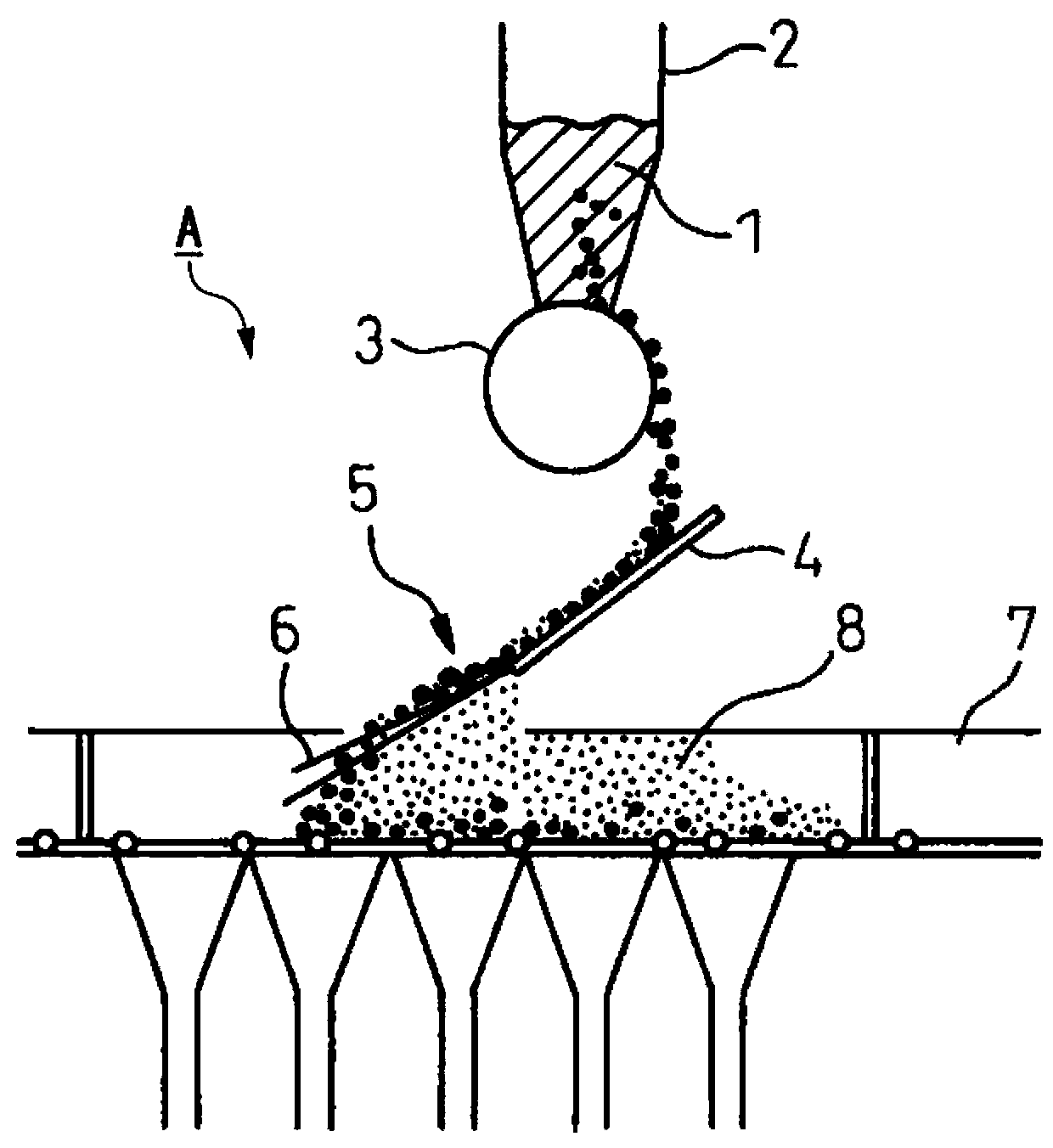
[0092] Hereinafter, an embodiment of an apparatus for charging raw materials for sintering according to the present invention will be described in detail with reference to the drawings. In addition, the downstream side in the flow direction of the sintering raw material is defined as the front, and the upstream side is defined as the rear.

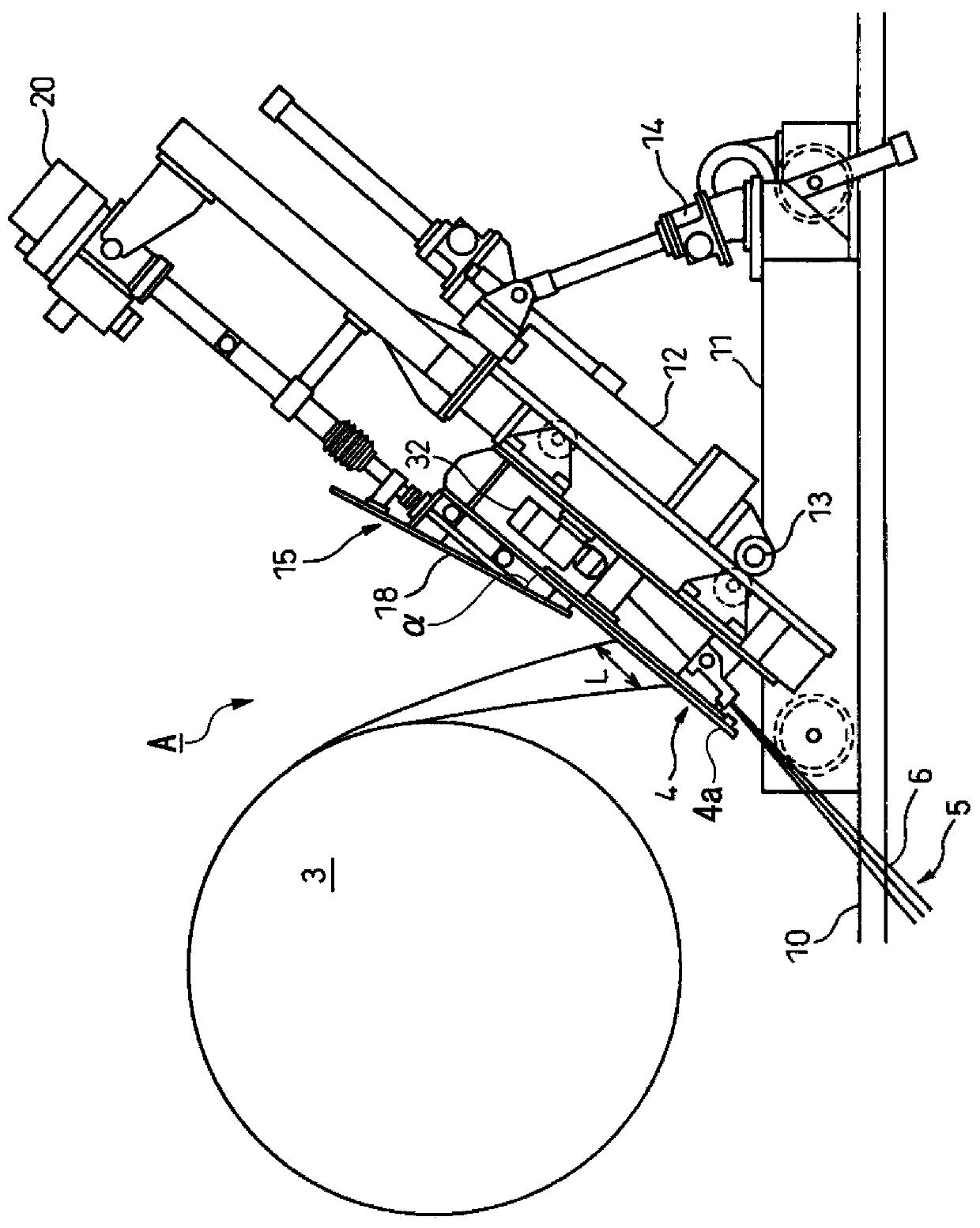
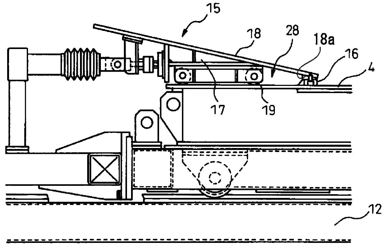
[0093] Such as figure 1 and figure 2 As shown, the loading device A for sintering raw materials is equipped with a guide groove 4 and a scraper 15 . The guide groove 4 is set between the barrel feeder 3 and the sintering trolley 7 of the sintering machine, and supplies (loads) the sintering raw materials taken out through the barrel feeder 3 onto the sintering trolley 7 . Such as figure 2 As shown, the guide trough 4 is mounted on a support trolley 11 that travels on a pair of rails 10 laid along the conveying direction of the sintering trolley 7 .

[0094] A tilt stand 12 capable of tilting the support guide groove 4 is attached to ...


PUM


Abstract

Provided is an apparatus for charging a sintering raw material, said apparatus comprising: a chute which charges the sintering raw material to a palette; and a scraper which moves back and forth on the chute and removes from the chute the sintering raw material that has accumulated on the chute. The scraper comprises: an inclined plate which is provided inclined with respect to the top surface of the chute; a scraping tool which is attached to the front end at the bottom surface side of the inclined plate; a support frame which supports the inclined plate; and a roller device which is attached to the support frame and causes the inclined plate and the support frame to travel on the top surface of the chute. The width dimension of the chute is at least substantially equal to the width dimension of the inclined plate.

Description

technical field [0001] The present invention relates to a device for loading sintered raw materials used when loading sintered raw materials onto a sintering trolley in a Dwight Lloyd sintering machine, in particular, to a sintering device having a guide groove for loading attached raw materials into a sintering car. Loading device for scraper for raw material removal. [0002] This application claims priority based on Japanese Patent Application No. 2010-056348 filed on March 12, 2010 in Japan and Japanese Patent Application No. 2010-056279 filed on March 12, 2010 in Japan, the contents of which are incorporated herein. Background technique [0003] In the sinter manufacturing process performed by the Dwight Lloyd sintering machine, the sintering raw material is taken out from the raw material hopper by a drum feeder, and loaded into the sintering trolley through a guide chute (also called a chute). [0004] At this time, more fuel (carbon source) is charged in the upper l...

Claims


Application Information

Patent Timeline
Patent Type & Authority Patents(China)
IPC IPC(8): F27B21/10
CPCF27B21/00F27D3/0033C22B1/20F27B19/00
Inventor 深仓佑二坪根洋平篠原贵司斋藤导宣
Owner NIPPON STEEL CORP
Learn More