Fully-hydraulic counter-blow hammer

A counter-hammer, fully hydraulic technology, applied in forging/pressing/hammer devices, forging/pressing/hammering machinery, power hammers, etc., can solve the problems of complex structure and linkage structure prone to failure, and achieve simple structure, The effect of improving accuracy

Inactive Publication Date: 2012-11-28
胡大勇
View PDF6 Cites 12 Cited by
  • Summary
  • Abstract
  • Description
  • Claims
  • Application Information

AI Technical Summary

Problems solved by technology

At present, the structures of these two linkage methods are rela

Method used


Image

  • Fully-hydraulic counter-blow hammer
  • Fully-hydraulic counter-blow hammer
  • Fully-hydraulic counter-blow hammer

Examples


Embodiment Construction

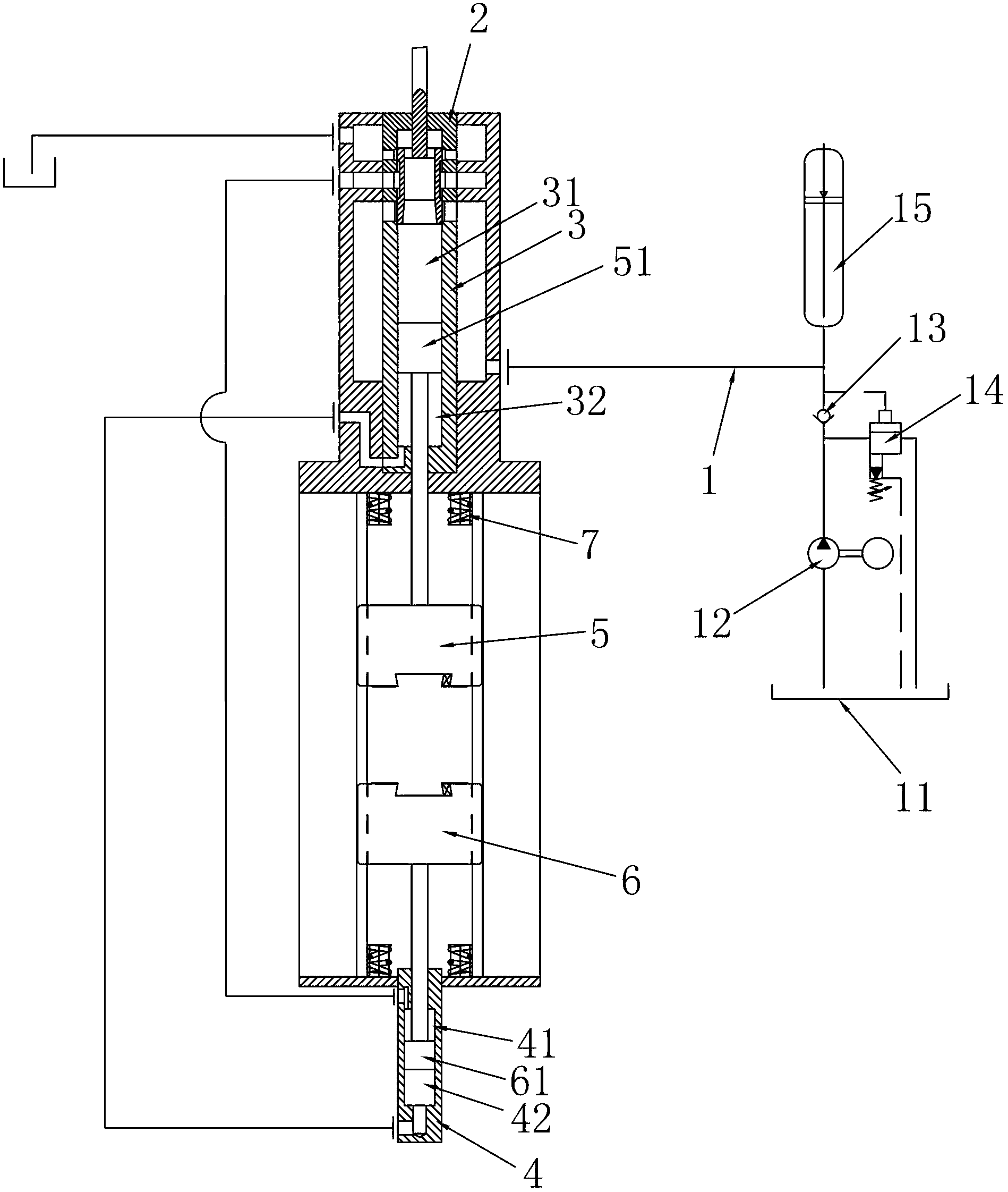
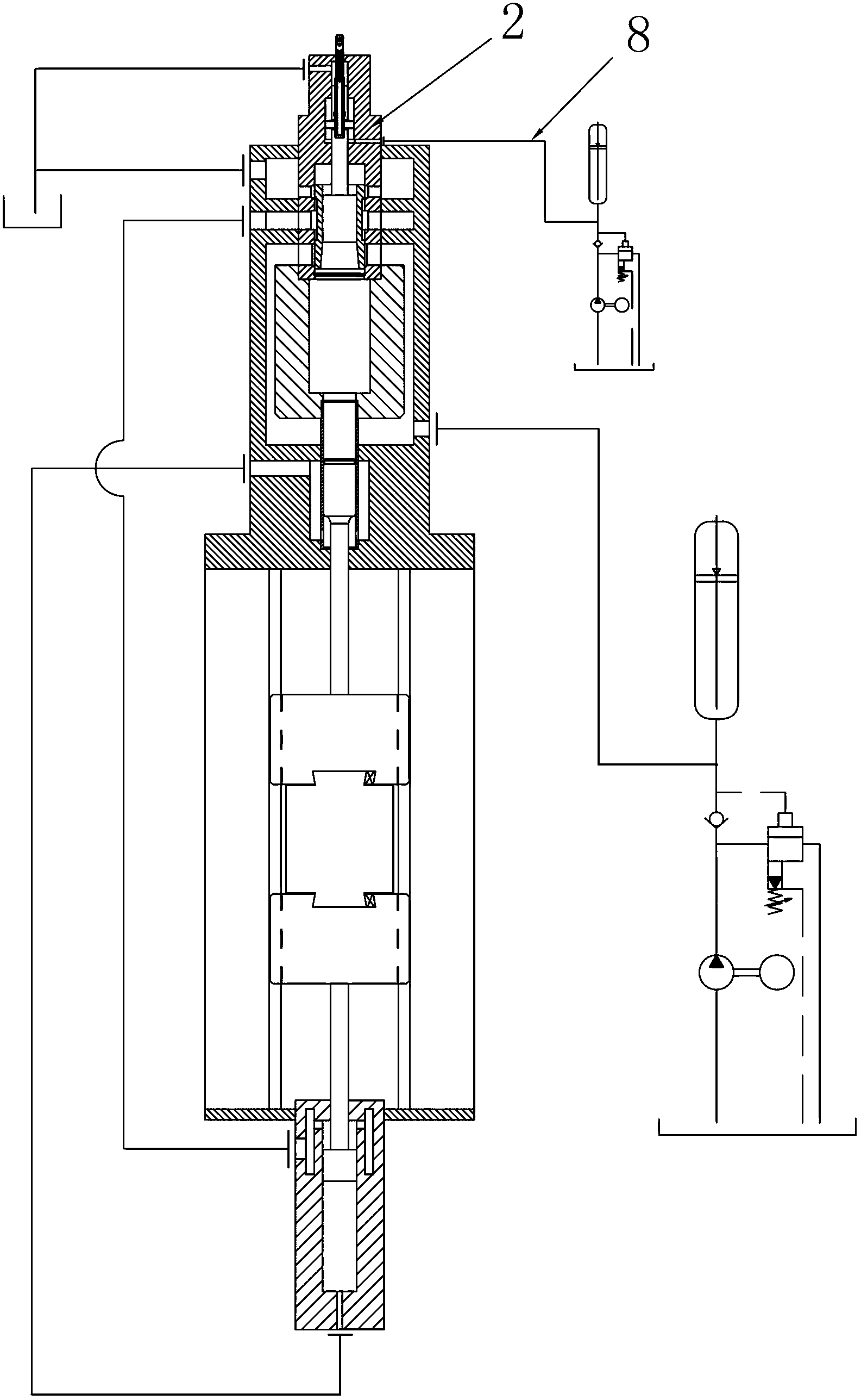
[0027] like figure 1As shown in the first embodiment of the full hydraulic counter hammer of the present invention, the upper hammer head 5 and the lower hammer head 6 are arranged vertically opposite each other, the upper hammer head 5 is connected to the upper hammer rod piston 51, and the lower hammer head 6 is connected to the lower hammer Rod piston 61, the upper hammer rod piston 51 is placed in the upper drive cylinder 3 and the upper drive cylinder 3 is divided into an upper drive upper cavity 31 and an upper drive lower cavity 32, and the lower hammer rod piston 61 is placed in the lower drive cylinder 4 and the lower drive cylinder 3 is divided into an upper drive upper cavity 31 and an upper drive lower cavity 32. The driving cylinder 4 is divided into a lower driving upper chamber 41 and a lower driving lower chamber 42. The upper driving lower chamber 32 is sealed and communicated with the lower driving lower chamber 42 to form a closed cavity, which is filled with...


PUM


Abstract

The invention discloses a fully-hydraulic counter-blow hammer, relates to forging and pressing equipment used in the forging industry, particularly relates to a counter-blow hammer driven hydraulically and provides a fully-hydraulic counter-blow hammer which is simpler in linkage structure and fewer in linkage fault. The fully-hydraulic counter-blow hammer provided by the invention comprises a hydraulic source (1), a control valve (2), an upper drive cylinder (3), a lower drive cylinder (4), an upper hammerhead (5), and a lower hammerhead (6), wherein the upper drive cylinder is divided into an upper drive upper cavity (31) and an upper drive lower cavity (32) via an upper hammer-rod piston (51); the lower drive cylinder is divided into a lower drive upper cavity (41) and a lower drive lower cavity (42) via a lower hammer-rod piston (61); the upper drive lower cavity (32) is hermetically connected to the lower drive lower cavity (42) to form an airtight accommodating cavity, and a liquid with a constant volume is fully filled in the airtight accommodating cavity; and the upper drive upper cavity (31) and the lower drive upper cavity (41) are switchably communicated with the hydraulic source (1) and an oil drainage channel respectively under the control of the control valve (2).

Description

technical field [0001] The invention relates to a forging equipment used in the forging industry, in particular to a hydraulically driven counter hammer. Background technique [0002] At present, in the forging industry, there is a full-hydraulic electro-hydraulic hammer, which controls the conversion between various hydraulic channels through control valves, so as to use hydraulic control machinery to work, such as application number 200610114757.9, publication number CN1986109, publication date It is an anti-crash hydraulic electro-hydraulic hammer disclosed in a Chinese invention patent on June 27, 2007. In addition, a Chinese utility model patent with an application number of 200620008003.0, a publication number of CN2892320, and a publication date of 2007.04.25 discloses a hydraulic hammer Electrohydraulic Hammer. Their main components include a hydraulic source, a fuselage, a control valve, a drive cylinder, and a hammer head connected to the hammer rod piston, as wel...

Claims


Application Information

Patent Timeline
IPC IPC(8): B21J7/28B21J7/46B21J13/06
Inventor 胡大勇
Owner 胡大勇
Why Eureka
Try Eureka