Slab continuous casting submersed nozzle

A slab continuous casting and immersion technology, which is applied in the field of continuous casting of steel, can solve the problems of unfavorable crystallizer lateral temperature and text uniformity, unfavorable mold temperature and composition uniformity, unfavorable inclusions and bubble floating removal, etc. problems, to achieve the effect of uniform solidification, continuous casting process improvement, avoiding remelting and damage

Active Publication Date: 2014-12-17
启东市长江船舶工业投资发展有限公司
View PDF6 Cites 0 Cited by
  • Summary
  • Abstract
  • Description
  • Claims
  • Application Information

AI Technical Summary

Problems solved by technology

[0005] Combined with the basic characteristics of the reasonable crystallizer flow field and temperature field mentioned above, it can be seen that when the existing double-sided hole submerged nozzle is used for pouring, the following three disadvantages usually exist: First, due to the high temperature molten steel flowing from the submerged nozzle After the inner cavity flows down vertically, it flows directly from the side hole, lacking the necessary buffer, so the impact velocity of the molten steel is very high, which will cause damage to the primary solidified billet shell on the narrow surface of the crystallizer, and will also cause remelting of the billet shell, which is not conducive to billet The normal growth of the shell; second, because the effective area of ​​molten steel flowing out from the side hole of the nozzle is small, the molten steel streams are relatively concentrated, and the local impact near the narrow side of the mold is relatively large, which may cause a meniscus near the narrow side Large fluctuations in the liquid level or slag entrainment appear on the liquid surface, and there will be a dead zone for molten steel flow near the nozzle. The state of liquid flow is also not conducive to the uniformity of the lateral temperature of the crystallizer and the text
Third, since the molten steel hits the narrow surface of the crystallizer, two backflows are formed. In most cases, the circulating flow of the molten steel in the lower part is more, which will make the temperature of the lower part of the mold higher and the temperature of the upper part lower. A reasonable temperature gradient is formed in the longitudinal direction, which deteriorates the internal quality of the slab and is not conducive to the floating removal of inclusions and bubbles in the molten steel
[0006] In the utility model patent with the notification number CN201082465Y, a submerged nozzle for continuous casting is disclosed. One of the important features of the submerged nozzle is that the outlet of the side hole of the nozzle has an extension section, which can play a better role. Diversion and buffering, however, because the extension of the side hole of the nozzle prevents the diffusion of molten steel, the stream at the outlet of the nozzle will more concentratedly impact the solidified shell on the narrow side of the crystallizer, destroying the normal growth of the narrow side of the shell At the same time, it is also very unfavorable for the uniformity of the molten steel temperature and composition in the transverse direction of the mold. Of course, it cannot maintain a reasonable pattern of high temperature in the upper part and low temperature in the lower part of the molten steel in the longitudinal direction. Therefore, the submerged nozzle is not effective. to solve the above disadvantages

Method used


Image

  • Slab continuous casting submersed nozzle
  • Slab continuous casting submersed nozzle
  • Slab continuous casting submersed nozzle

Examples


Embodiment Construction

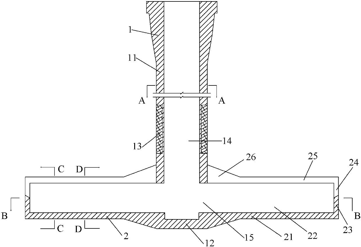
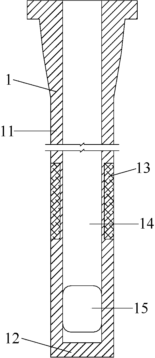
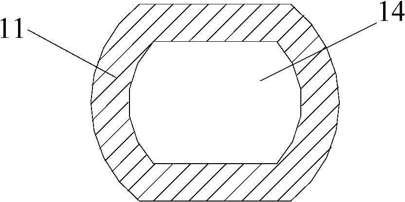
[0031] Below in conjunction with specific embodiment of the present invention and description attached Figure 1-8 The technical scheme of the present invention will be further described.

[0032] Such as Figure 1 to Figure 6 As shown, the slab continuous casting submerged nozzle involved in the present invention is composed of a vertical section 1 and a horizontal section 2. The vertical section 1 includes a side wall 11 and a closed bottom 12. On the outer side of the side wall 11 A ring-shaped slag line 13 is provided, the depth of the slag line 13 is 10-25 mm, the height is 100-160 mm, and the distance between the lower end of the slag line 13 and the lower surface of the nozzle bottom 12 is 60-120 mm; the side wall 11 and The bottoms 12 are connected to each other and form a hollow cavity 14 with an open top in the vertical direction. The cross-sectional shape of the side wall 11 and the hollow cavity 4 can be circular, square with chamfered corners or flat front and ba...


PUM


Abstract

The invention relates to a slab continuous casting submersed nozzle. The slab continuous casting submersed nozzle consists of a vertical section and a horizontal section; a pair of side holes are formed in the side wall close to the upper side of the bottom of the slab continuous casting submersed nozzle; two side holes are communicated with a hollow inner cavity; the wall surfaces around the side holes extend in the horizontal direction to form the horizontal section; the wall surface of the horizontal section forms a tubular pipeline the shape of which is identical to that of the side holes in an encircling manner; one end of the tubular channel is connected with the side holes; the other end of the tubular channel forms the semi-sealed surface; and an elongated opening identical to the length of the horizontal section is formed in the wall surface of the upper end of the tubular channel. According to the technical scheme, a steel liquid flowing channel is enlarged, and the steel liquid can be fully diffused to the cross section of the whole crystallizer, so that the transverse temperature of the crystallizer and the uniformity of components are guaranteed to ensure that the heat center of high-temperature steel liquid subjected to pouring is moved upwards; a reasonable temperature trapezoid is guaranteed; the normal growth of casting blank is facilitated; flotation removal of nonmetallic inclusion and bubbles is facilitated; the remelting and the destroy of a blank shell is avoided; the disturbance of the steel liquid on the liquid level of the crystallizer is reduced; the smoothness of continuous casting process is facilitated; and the quality of the casting blank is improved.

Description

technical field [0001] The invention belongs to the technical field of continuous casting of steel, more precisely, relates to a slab continuous casting submerged nozzle. Background technique [0002] Continuous casting of steel is the process of continuously cooling molten steel with a certain degree of superheat through a water-cooled crystallizer into a solid billet with a certain shape. The metallurgical container is injected into the crystallizer, and the refractory sleeve is called the submerged nozzle; the upper end of the submerged nozzle is vertically installed at the bottom of the upstream metallurgical container, and the lower end is inserted below the liquid steel surface of the mold. Secondary oxidation, nitriding, and splashing, while avoiding slag rolling on the liquid surface, adjusting the flow pattern and temperature distribution of the molten steel in the mold, so as to promote the uniform and defect-free growth of the billet shell in the mold, and minimiz...

Claims


Application Information

Patent Timeline
Patent Type & Authority Patents(China)
IPC IPC(8): B22D41/50
Inventor 徐海伦青雪梅马春武幸伟徐永斌
Owner 启东市长江船舶工业投资发展有限公司
Why Eureka
Try Eureka