H-shaped steel turning device

A turning device and H-shaped steel technology, which is applied in auxiliary devices, auxiliary welding equipment, welding/cutting auxiliary equipment, etc., can solve the problems of complicated H-shaped steel process, low production efficiency, casualties, etc., and achieve high turning operation efficiency and improved Effects of productivity, labor saving and operating time

Inactive Publication Date: 2012-11-28
HUBEI HONGYI BUILDING DECORATION ENG
View PDF6 Cites 23 Cited by
  • Summary
  • Abstract
  • Description
  • Claims
  • Application Information

AI Technical Summary

Problems solved by technology

[0002] The production process of H-shaped steel is cumbersome, and there is no special H-shaped steel turning equipment at present. The existing H-shaped steel needs to turn over the H-shaped steel during the assembly and welding process. The traditional turning is to rely on the truss truck to lift and cooperate with manual Flip
The operation steps of using the truss truck to turn over the steel are cumbersome and complicated, and many employees need to cooperate near the workpiece. The whole turning process is time-consuming and laborious, and the production efficiency is relatively low. In addition, during the whole turning process, the H-shaped steel slips from the truss car. risk of personal injury

Method used


Image

  • H-shaped steel turning device
  • H-shaped steel turning device
  • H-shaped steel turning device

Examples


Embodiment Construction

[0017] Now further illustrate how the present invention is implemented in conjunction with the accompanying drawings:

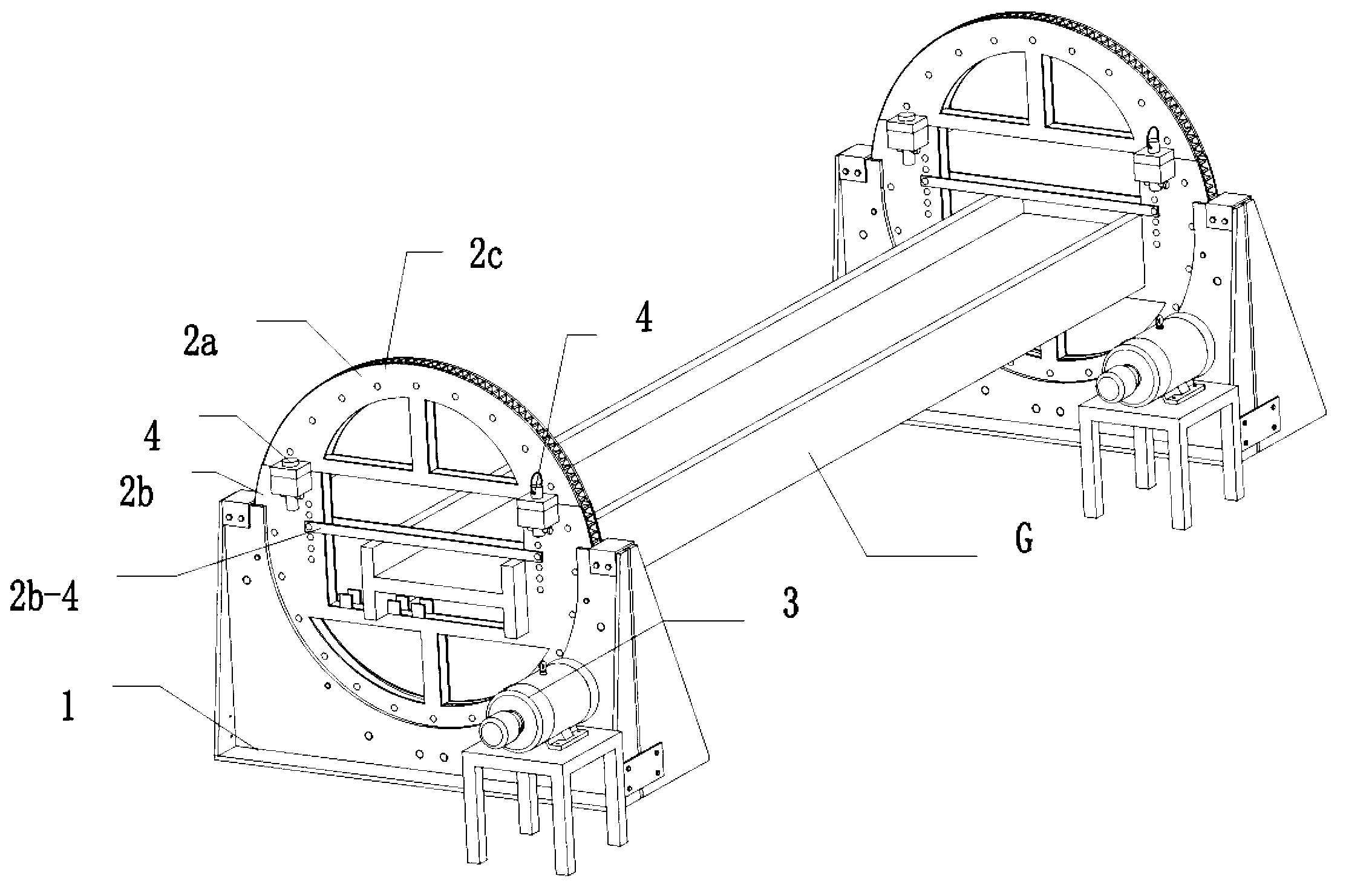
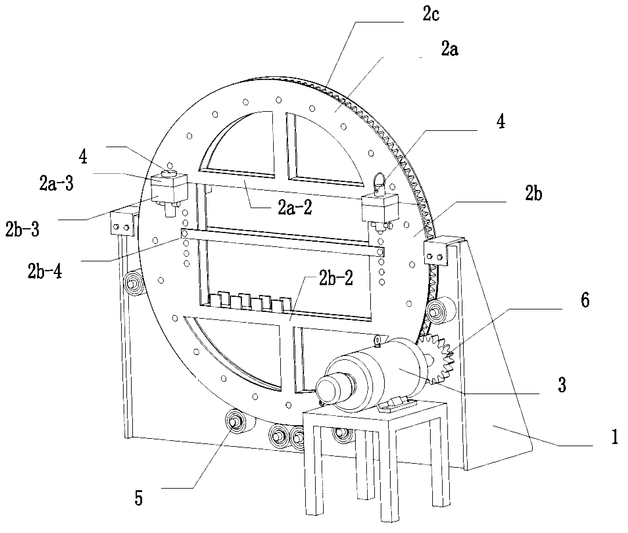
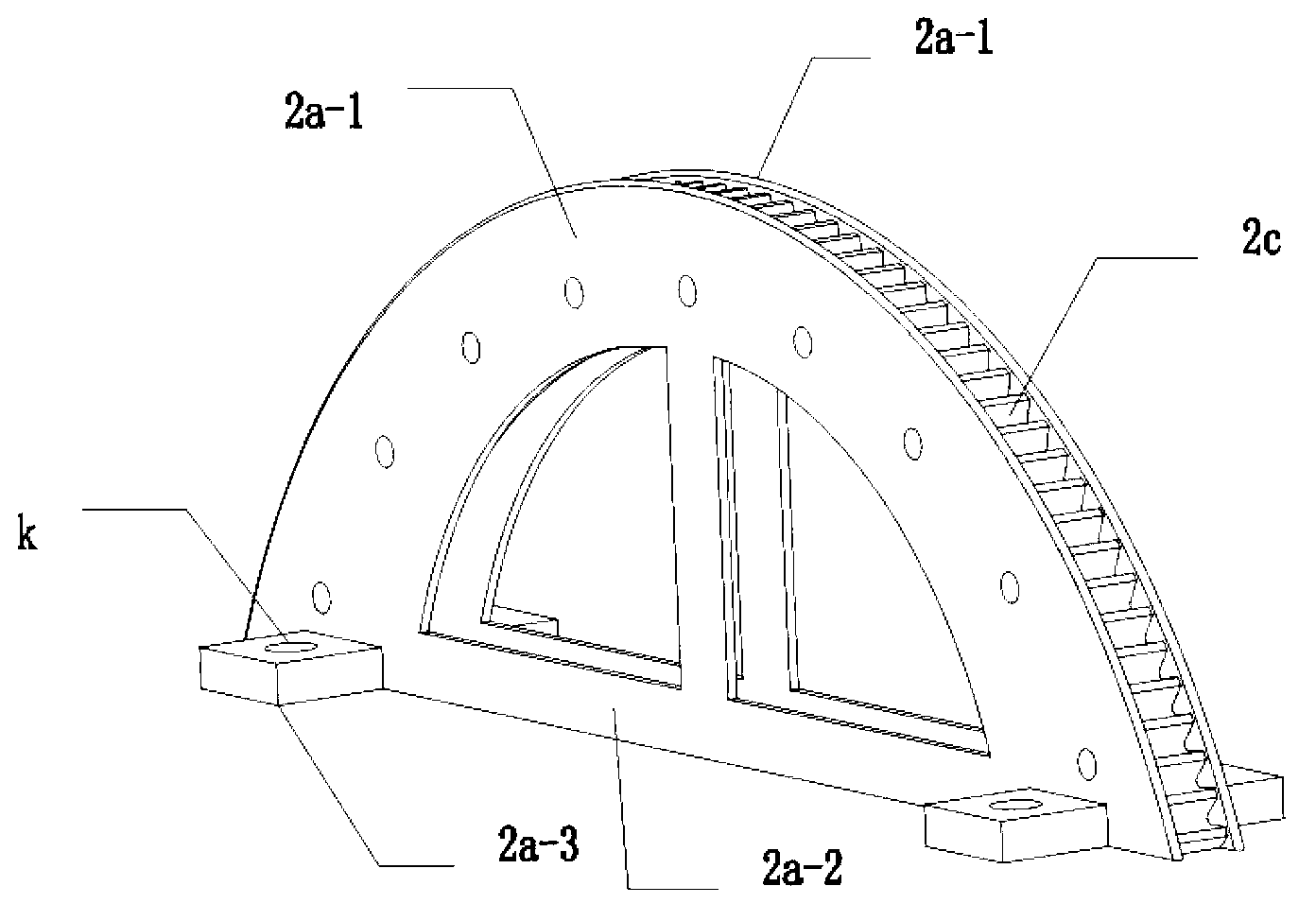
[0018] The turning machine of the H-beam turning device of the present invention is composed of a base 1, a turning frame 2 and a motor unit 3. The turning frame is an arc-shaped turning frame composed of an upper frame 2a and a lower frame 2b, and the rack 2c of the upper frame is embedded and clamped The two arc splints 2a-1 are fixedly connected to form an integral body between the arc peripheries of the two arc splints. The two arc splints 2a-1 on the upper frame correspond to the chord beam 2a-2 and the pin shaft connecting platform 2a-3 respectively; The rack 2c is embedded and fixed between the arc circumferences of the two arc splints 2b-1 to form a whole, and the two arc splints 2b-1 of the lower frame 2b respectively correspond to the bottom beam 2b-2 and the pin shaft connection platform. 2b-3, the movable outer baffle 2b-4, on the bottom beam 2b-2...


PUM


Abstract

The invention discloses an H-shaped steel turning device and belongs to the field of a frock machine tool of a machine. The H-shaped steel turning device comprises two same turning machines, wherein the turning machine comprises a base, a turning frame and a motor; the turning frame is an open-close type round turning frame comprising an upper frame body and a lower frame body connected through a pin shaft; racks are embedded along the arc peripheries of the upper frame body and the lower frame body respectively; an H-shaped steel frame position is formed between the upper frame body and the lower frame body; the periphery of the turning frame is arranged in an arc-shaped track of the base in a matched way; the motor is engaged with the racks on the periphery of the round turning frame through a small gear of an output shaft of the motor so as to drive the turning frame to rotate; the two ends of H-shaped steel are respectively mounted in the H-shaped steel frame positions of the two turning machines; and the two turning machines adopt synchronous motors and drive the two turning frames to synchronously rotate with the H-shaped steel. The H-shaped steel can be turned through the device without a travelling crane and large quantities of auxiliary labors, so that the turning efficiency is high, the labor force and the operation time are saved, the operation is safe and convenient, and the production efficiency of products is improved.

Description

technical field [0001] The H-shaped steel turning device of the invention belongs to the field of mechanical tools. Background technique [0002] The production process of H-beam is cumbersome. At present, there is no dedicated H-beam turning equipment. The existing H-beam needs to be turned over during the assembly and welding process. achieve flip. The operation steps of turning the section steel with the truss car are cumbersome and complicated, and multiple employees are required to cooperate in the vicinity of the workpiece. The entire turning process is time-consuming and laborious, and the production efficiency is relatively low. In the entire turning process, there are H-beams slipping from the truss car. Risk of personal injury or death. SUMMARY OF THE INVENTION [0003] The purpose of the present invention is to provide an H-section steel overturning device, which can directly overturn the section steel, omit auxiliary labor, simplify the section steel overturn...

Claims


Application Information

Patent Timeline
Patent Type & Authority Applications(China)
IPC IPC(8): B23K37/047
Inventor 吴顺红张军魏巍王少重
Owner HUBEI HONGYI BUILDING DECORATION ENG
Why Eureka
Try Eureka