Novel pump impeller

A technology for pumps and impellers, which is applied in the field of new pump impellers, can solve the problems that centrifugal pumps are not easy to carry, increase the complexity of centrifugal pump structures, etc., and achieve the effect of light structure, simplified structure and easy use

Inactive Publication Date: 2012-11-28
苏州市世强流体技术有限公司
View PDF7 Cites 4 Cited by
  • Summary
  • Abstract
  • Description
  • Claims
  • Application Information

AI Technical Summary

Problems solved by technology

[0003] Before the water pump works, the pump body and the water inlet pipe must be filled with water, and then rely on the high-speed rotating impeller to make the liquid gain energy under the action of inertial centrifugal force to increase its internal pressure. When the impeller rotates rapidly, the blades promote the water to rotate quickly , the rotating water flies away from the impeller under the action of centrifugal force. After the water in the pump is thrown out, the central part of the impeller forms a vacuum area, and then the water from the water source passes through the tube under the action of atmospheric pressure (or water pressure). The net is pressed into the water inlet pipe, so that the circulation is endless, and continuous pumping can be realized, because it has the advantages of simple structure, easy operation, easy flow adjustment, and is suitable for the transportation of various special materials. In order to achieve a certain pumping effect, Currently commonly used as figure 1 The multi-stage centrifugal pump shown is for pumping water, which requires multiple impellers to rotate, so a coupling is required to connect multiple impellers, which greatly increases the complexity of the entire centrifugal pump structure and makes the centrifugal pump difficult to carry

Method used


Image

  • Novel pump impeller
  • Novel pump impeller

Examples


Embodiment Construction

[0013] Below in conjunction with accompanying drawing and embodiment the invention is described in detail:

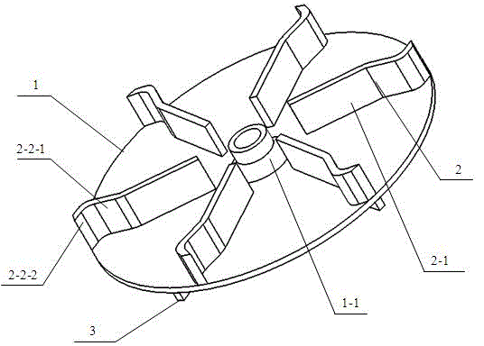
[0014] The present invention improves the structure of the existing impeller by designing a new type of pump impeller, so that the drainage pump can achieve a high lift with a single impeller, so the impeller described in this patent does not need to be installed on the power output shaft of the engine without a coupling It can be used directly on the screen, which greatly simplifies the structure of the centrifugal pump.

[0015] As a specific embodiment of the present invention, the present invention provides a structural schematic diagram such as figure 2 A new type of pump impeller shown includes a cover plate 1, a front blade 2 and a rear blade 3. There is a connecting portion 1-1 in the middle of the cover plate 1, and the portable pump impeller passes through the connecting portion on the cover plate 1. 1-1 is installed on the power output shaft of the engine. ...


PUM


Abstract

The invention provides a novel pump impeller. The novel pump impeller comprises a cover plate, a front blade and a rear blade, wherein a connecting part is arranged in the middle of the cover plate; the portable pump impeller is arranged on a power output shaft of an engine through the connecting part on the cover plate; the front end face of the cover plate is provided with at least three front blades at equal angles; the rear end face of the cover plate is provided with at least three rear blades at equal angles; the cover plate, the front blade and the rear blade are integrally formed; the front blade comprises a blade front end part and a blade rear end part; the blade rear end part is bent in the counter clockwise direction; and an included angle is formed between the blade front end part and the blade rear end part. According to the novel pump impeller, the conventional impeller structure is improved, so that a draining pump can reach a high lift just by using a single impeller. Therefore, the impeller can be directly installed on the power output shaft of the engine for use without a shaft coupling, so that the structure of a centrifugal pump can be greatly simplified.

Description

technical field [0001] The invention relates to the field of centrifugal pump accessories, in particular to a novel pump impeller. [0002] Background technique [0003] Before the water pump works, the pump body and the water inlet pipe must be filled with water, and then rely on the high-speed rotating impeller to make the liquid gain energy under the action of inertial centrifugal force to increase its internal pressure. When the impeller rotates rapidly, the blades promote the water to rotate quickly , the rotating water flies away from the impeller under the action of centrifugal force. After the water in the pump is thrown out, the central part of the impeller forms a vacuum area, and then the water from the water source passes through the tube under the action of atmospheric pressure (or water pressure). The net is pressed into the water inlet pipe, so that the circulation is endless, and continuous pumping can be realized, because it has the advantages of simple str...

Claims


Application Information

Patent Timeline
IPC IPC(8): F04D29/22F04D29/24
Inventor 李世煌王强
Owner 苏州市世强流体技术有限公司
Why Eureka
Try Eureka